
User manual
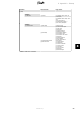


Main Menu Horizontal menu Page content
↳
Submenu
[0] Grid management
2
[0] Power level adjustment
[0] Power level adjustment: %
[0] Current production: W
[0] Frequency stabilization
[0] Maximum power: W
[0] Activation frequency: Hz
[0] Slope: %
[0] Deactivation frequency: Hz
[0] Inverter [0] General
[0] Country:
[0] Language:
[0] Inverter name:
[0] Inverter group name:
[0] Inverter operation mode:
[0] Installation date:
[0] Inverter model:
[0] Inverter serial number:
[0] Inverter product number:
[0] Inverter SW version:
[0] MAC address:
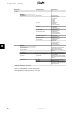
[1] DC bus voltage
[1] Upper: V
[1] Maximum upper: V
[1] Lower: V
[1] Maximum lower: V
[0] PCB temperatures
[0] PCB 1 (Aux): °C
[1] PCB 2 (Ctrl): °C
[1] PCB 3 (Pow): °C
[0] PCB 1 Max (Aux): °C
[1] PCB 2 Max (Ctrl): °C
[1] PCB 3 Max (Pow): °C
[1] Internal conditions – RPM
of fans
[1] Fan 1: RPM
[1] Fan 2: RPM
[1] Fan 3: RPM
[1] Fan 4: RPM
[0] Power module tempera-
tures
[0] Power module 1: °C
[1] Power module 2: °C
[1] Power module 3: °C
[1] Power module 4: °C
[1] Power module 1 Max: °C
[1] Power module 2 Max: °C
[1] Power module 3 Max: °C
[1] Power module 4 Max: °C
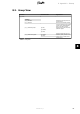
[0] PCB Serial numbers
Power board serial number
[0] POW
AUX board serial number
[0] AUX
Com board serial number
Control board serial number
[0] CTRL[0] COMM
[0] PCB product numbers
Power board part number
[0] POW
AUX board part number
[0] AUX
Control board part number
[0] CTRL
Com board part number
[0] COMM
[0] PCB software versions
Control board
[0] CTRL
Functional safety processor
[0] FSP
Display software version
[0] DISP
Communication board
[0] COMM
Table 8.7: Inverter View - Continued
8. Appendix A - Sitemap
64 L00410583-01_02
8