
User manual


Content of E-mail Notification
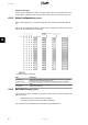
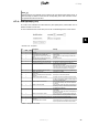
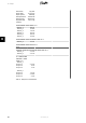
Item Unit Description
Plant name - The name of the plant.
Report date dd-mm-yyyy The reporting date.
Report period - The reporting period: daily, weekly, monthly.
Plant production kWh Energy of the entire plant delivered to the utility grid during
the reporting period.
Plant revenue Euro The total revenue for the reporting period.
Equivalent CO
2
emission kg The total CO
2
saved for the reporting period
Performance ratio % A coloured bullet indicates the status of the system. See the
section
Plant, Group and Inverter Views
for an explanation of
status.
Red: Plant PR < 50 %, or:
Any inverter in the network
- in
fail safe
mode, or
- missing from the scan list, no contact with the master
Yellow: Any inverter in the network
- with PR < 70 %, or
- in
Connecting
or
Off grid
mode
Green: Plant PR ≥ 70 %, and
- all inverters with PR ≥ 70 %, and
- all inverters in
On grid
mode
An irradiation sensor must be installed before the perform-
ance ratio can be calculated.
Inverter income deviation - A notification is issued if an inverter has produced insufficient
energy compared to the remaining inverters during the re-
porting period.
The message will contain a list of inverters producing insuffi-
cient energy. If there are no events, the following text is
shown:
All inverters operating OK
.
PV income deviation - A notification is issued if one of the PV strings has produced
insufficient energy compared to the remaining strings during
the reporting period.
The message will contain a list of inverters and the corre-
sponding PV string, where the production comparison has is-
sued the notification. If there are no events, the following text
is shown:
All strings operating OK
.
Inverter event List of inverters which have had events. If there are no errors,
the following text is shown:
All inverters operating OK
.
Table 6.3: Content of E-mail Notification
6.8.
Date and Time
[0] [Plant]
See section
Setup, Inverter details, Data and Time
.
6.9.
Security
[0] [Plant, Inverter]
Enter the security password here.
The password defines the user security level , ranging from 1 to 3.
Changing the security level via the master changes the security level for every inverter in the
network.
The current user access level is displayed in the footer of the Web Server, as Security Level xx.
6. Setup
L00410583-01_02 49
6