
Technical data

1. To help prevent a complete voltage black-out and stabilise the voltage in the grid.
2. To increase the energy delivered to the AC grid.
The inverter has a high immunity against voltage disturbances as depicted below.
10.5.1. Example
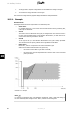
How FRT works
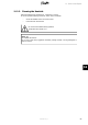
The diagram below shows the requirements to be followed by FRT.
• Above line 1
For voltages above line 1, the inverter must not disconnect from the grid during FRT,
under any circumstances.
• Area A
The inverter must not disconnect from grid, for voltages below line 1 and left of line 2.
In some cases the DNO permits a short-duration disconnection, in which case the in-
verter must be back on grid within 2 seconds.
• Area B
To the right of line 2, a short-duration disconnection from grid is always permitted.
The reconnect time and power gradient can be negotiated with the DNO.
• Below line 3
Below line 3, there is no requirement to remain connected to grid.
When a short-duration disconnection from grid occurs,
- the inverter must be back on grid after 2 seconds;
- the active power must be ramped back at a minimum rate of 10% of nominal
power per second.
Illustration 10.6: Example
Note:
For inverters connected to their own distribution transformer, select a grid code ending in
MV. This enables dynamic voltage control. That is, reactive current during FRT.
10. Ancillary Services
92 L00410582-01_02
10