
Technical data

8.3. Peripheral Units Setup
8.3.1. Sensor Setup
This section describes the final step of configuring the sensor inputs using the display or the
Web Server. Go to the Calibration menu under Setup [Setup → Calibration] and choose the sen-
sor to be configured.
Temperature Sensor
The temperature sensor inputs for the PV module temperature and the ambient temperature
may be calibrated using an offset ranging from -5.0 to 5.0 °C. Enter the correct values for the
sensors under the Temp. sensor offset menu [Setup → Calibration → Temp. sensor offset].
Irradiation Sensor (Pyranometer)
In order to use an irradiation sensor, the scale and temperature coefficient of the sensor must
be entered. Enter the correct values for the sensor at [Setup → Calibration → Irradiation sen-
sor].
Energy Meter (S0 sensor)
In order to use an energy meter (S0 sensor), the scale of the energy meter must be entered in
pulses/kWh. This is done under the S0 sensor input menu [Setup → Calibration → S0 sensor in-
put]
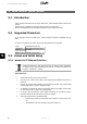
8.3.2. Alarm Output
By default the alarm functionality is disabled.
To activate the alarm,
-
go to [Setup → External alarm → Alarm state] and select 'Enabled'
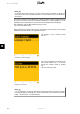
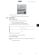
The alarm functionality can also be tested from this menu. If the alarm is triggered, it will re-
main active for the period of time defined under Alarm time-out (the value 0 disables the time-
out functionality and the alarm will sound continuously). While the alarm is active it may be
stopped at any time . To stop the alarm go to [Setup → External alarm] pressing OK twice, thus
selecting and accepting.
• Stop alarm
• Test alarm
• Alarm state
• Alarm time-out
The alarm is activated by any of the following events:
Event ID Description
40 The AC grid has been out of range for more than 10 minutes.
115 The insulation resistance between ground and PV is too low. This will force the in-
verter to make a new measurement after 10 minutes.
233-240 Internal memory error
241, 242 Internal communication error
243, 244 Internal error
251 The functional safety processor has reported Fail safe
350-364 An internal error has set the inverter in Fail safe
Table 8.11: Activation of Alarm
8. User Interface
70 L00410582-01_02
8