
Technical data
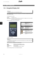
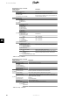

8.1.5. Setup
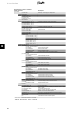
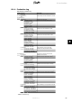
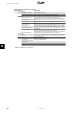
Menu Structure - Setup
Display Functions Description
[0] External Alarm Only applicable if external alarm is connected
[0] Stop Alarm Stop alarm
[0] Test Alarm Includes testing red LED on front
[0] Alarm state: Disabled
[0] Alarm time-out:
009 s alarm time limit. If 0, the alarm will be active until
fixed
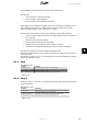
[0] Setup details
[0] Language:
The language in the display; changing the language does not
affect the grid code
[2] Grid code: The grid code, which defines functional safety settings
[2] Safety affecting settings Settings that have influence in functional safety
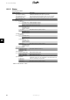
[2] 10 min. mean voltage
[2] Avg. voltage limit: 253 V Upper 10 min. average voltage limit
[2] Time to disconnect: 200 ms
Maximum amount of time before the inverter must discon-
nect from the grid due to too high avg voltage
[2] ROCOF ROCOF: Rate of Change of Frequency
[2] ROCOF limit: 1.50 Hz/s
[2] Time to discon.: 200 ms
[1] PV Configuration See the section on
Parallel connection
[1] Mode: Automatic May be changed to
Manual
if the automatic PV configuration
is to be overridden
[1] PV input 1: Automatic
[1] PV input 2: Automatic
[1] PV input 3: Automatic
[1] Force inverter power up Turns on grid supply to CTRL board
[0] Inverter details
[0] Inverter name: The inverter's name. Max. 15 characters
Danfoss Max. 15 characters and not only numbers
[0] Group name: The name of the group the inverter is part of
[0] Group 1 Max. 15 characters.
[0] Master mode
[0] Master mode: Enabled
[0] Network Only visible if Master mode is enabled.
[0] Initiate network scan
[0] Scan progress: 0%
[0] Inverters found: 0
[0] Plant name: The name of the plant. Max. 15 characters.
plant name
[1] Reset max. values
[1] Set date and time
[1] Date: yyyy-mm-dd (2010-12-30) Set the current date
[1] Time: hh.mm.ss (13.45.27) Set the current time
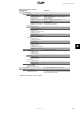
[0] Calibration
[0] PV array
[0] PV input 1: 6000 W
[0] PV 1 area: 123 m
2
[0] PV input 2 : 6000 W
[0] PV 2 area: 123 m
2
[0] PV input 3: 6000 W Not visible if inverter only has 2 PV inputs.
[0] PV 3 area: 123 m
2
Not visible if inverter only has 2 PV inputs.
[0] Irradiation sensor
[0] Scale (mV/1000 W/m
2
): 75
Sensor calibration
[0] Temp. coeff: 0.06 %/
o
C
Sensor calibration
[0] Temp. sensor offset
[0] PV module temp: 2
o
C
Sensor calibration (offset)
[0] Ambient Temp: 2
o
C
Sensor calibration (offset)
[0] S0 sensor input
[0] Scale (pulses/kWh): 1000 Sensor calibration. See note
Table 8.8: Setup
8. User Interface
L00410582-01_02 67
8