
Technical data
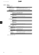
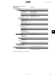
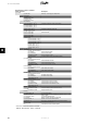
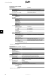

Menu Structure - Status - Continued
Display Functions Description
[0] Inverter
[0] Grid code: Read only. To change go to Setup menu
[1] DC-bus voltages
[1] Upper: 400 V
[1] Max upper: 500 V
[1] Lower: 400 V
[1] Max lower: 500 V
[0] Internal Conditions
[0] Power module 1: 100
o
C
Temperature detected at the power module
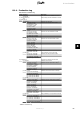
[1] Power module 2: 100
o
C
[1] Power module 3: 100
o
C
[1] Power module 4: 100
o
C
[0] PCB 1 (Aux): 100
o
C
Temperature detected at the PCB
[1] PCB 2 (Ctrl): 100
o
C
[1] PCB 3 (Pow): 100
o
C
[0] Fan 1: 6000 RPM Speed of the fan
[1] Fan 2: 6000 RPM
[1] Fan 3: 6000 RPM
[1] Fan 4: 6000 RPM
[1] Max values
[1] Power module 1: 100
o
C
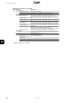
[1] Power module 2: 100
o
C
[1] Power module 3: 100
o
C
[1] Power module 4: 100
o
C
[1] PCB 1 (Aux): 100
o
C
[1] PCB 2 (Ctrl): 100
o
C
[1] PCB 3 (Pow): 100
o
C
[0] Serial no. and SW ver.
[0] Inverter
[0] Prod- and serial number:
[0] 123A4567 Inverter product number
[0] 123456A789 Inverter serial number
[0] Software version: Inverter software version
[0] MAC address: The MAC address of the communication board
[0] ...
[0] Control board
[0] Part-and serial number:
[0] 123A4567 Control board part number
[0] 123456A789 Control board serial number
[0] Software version: Control board software version
[1] Operating time: 1h
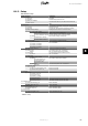
[0] Power board
[0] Part-and serial number:
[0] 123A4567 Power board part number
[0] 123456A789 Power board serial number
[1] Operating time: 1h
[0] AUX board
[0] Part-and serial number:
[0] 123A4567 Aux board part number
[0] 123456A789 Aux board serial number
[1] Operating time: 1h
[0] Communication board
[0] Part-and serial number:
[0] 123A4567 Communication board part number
[0] 123456A789 Communication board serial number
[0] Software version: Communication board software version
[1] Operating time: 1h
[0] Func. Safety Processor
[0] Software version: Functional Safety processor software version
[0] Display
[0] Software version: Display software version
[0] Upload status
[0] Upload status: Off Current upload status
[0]* Signal strength: Signal strength. Should preferably be between 16-31. '-' Indi-
cates no signal
[0]* GSM status: None Current GSM network status
[0]* Network: Network to which the modem is connected
[0] Failed uploads: 0 Number of consecutive failed uploads
[0] Last error: 0 Last error ID, see the GSM Manual for further assistance
[0] - Time and date of last error
[0] Last upload:
[0] - Time and date of last successful upload
* Visible when communication channel is set to GSM.
Table 8.5: Menu Structure - Status - Continued
8. User Interface
64 L00410582-01_02
8