
Technical data
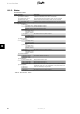
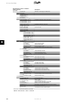
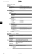

Menu Structure - Status - Continued
Display Functions Description
[0] AC-grid
[0] Present Values
[0] Phase 1
[0] Voltage: 250 V Voltage on phase 1
[1] 10 min. mean: 248 V Average voltage sampled over 10 min. on phase 1
[1] L1-L2: 433 V Phase to phase voltage
[0] Current: 11.5 A Current on phase 1
[1] DC-cont of current: 125 mA DC content of AC-grid current on phase 1
[0] Frequency: 50 Hz Frequency on phase 1
[0] Power: 4997 W Power on phase 1
[1] Apparent P. (S): 4999 VA Apparent power (S) on phase 1
[1] Reactive P. (Q): 150 VAr Reactive power (Q) on phase 1
[0] Phase 2
[0] Voltage: 250 V
[1] 10 min. mean: 248 V
[1] L2-L3: 433 V
[0] Current: 11.5 A
[1] DC-cont of current: 125 mA
[0] Frequency: 50 Hz
[0] Power: 4997 W
[1] Apparent P. (S): 4999 VA
[1] Reactive P. (Q): 150 VAr
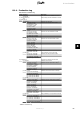
[0] Phase 3
[0] Voltage: 250 V
[1] 10 min. mean: 248 V
[1] L3-L1: 433 V
[0] Current: 11.5 A
[1] DC-cont of current: 125 mA
[0] Frequency: 50 Hz
[0] Power: 4997 W
[1] Apparent P. (S): 4999 VA
[1] Reactive P. (Q): 150 VAr
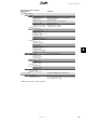
[1] Maximum values of AC Maximum values registered
[1] Phase 1
[1] Voltage: 250 V
[1] Current: 11.5 A
[1] Power: 4997 W
[1] Phase 2
[1] Voltage: 250 V
[1] Current: 11.5 A
[1] Power: 4997 W
[1] Phase 3
[1] Voltage: 250 V
[1] Current: 11.5 A
[1] Power: 4997 W
[0] Residual Current Monitor
[0] Current: 350 mA
[1] Maximum value: 350 mA
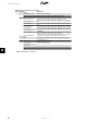
[0] Grid management Only visible if enabled by the current grid code.
[0] Power level adjustment
[0] Present limit: 100 %
Maximum allowed power output in % of nominal power out-
put. “Off” means that the power level adjustment functionality
has been disabled in the inverter.
Table 8.4: Menu Structure - Status - Continued
8. User Interface
L00410582-01_02 63
8