
Technical data

1. M16: Other peripheral units (sensors, alarm outputs and RS485 peripheral which inter-
face the terminal block).
2. M25: For RS485 and Ethernet peripheral units which apply RJ45 plugs.
7.2.1. RS485 Peripheral and Ethernet Units which apply RJ45
1. Unscrew the blind plugs.
2. Place the M25 cable gland in the cabinet, add the nut and fasten the cable gland.
3. Unscrew the cap of the cable gland and slide it over the cable(s).
4. The special M16 plug provided in the scope of delivery allows one or two cables with
pre-assembled RJ45 plugs to be applied. Adapt the M16 plug as follows:
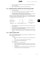
According to the number of RS485 or Ethernet cables, cut one or two rubber knob(s) and one
or two slot(s) in the side of the sealing insert as indicated with * in the following illustrations.
This enables the cable(s) to be inserted from the side.
Illustration 7.3: Cut a Slot Illustration 7.4: Sealing Insert Side View
Illustration 7.5: Cut Rubber
Knob
1. Add the adapted plug to the cable(s) and insert the cable(s) with RJ45 plug through
the cable gland hole.
2. Mount the RJ45 plug in the RJ45 socket as shown in the illustration:
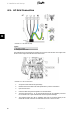
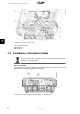
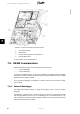
Auxiliary Connec-
tion Area
, arrow (1) and fasten the cable gland cap.
3. Optionally the EMC cable clamp (illustration
Auxiliary Connection Area
, arrow (4)) can
be used for a mechanical fixation of the cable – provided that some of the 6 clamps
are free.
7.2.2. Other Peripheral Units
Sensors, alarms and RS485 peripheral units which are applied to the terminal block must use
M16 cable glands and EMC cable clamps.
Cable gland:
1. Place the M16 cable gland in the cabinet, add the nut and fasten the cable
gland.
2. Unscrew the cap of the cable gland and slide it over the cable.
3. Insert the cable through the cable gland hole.
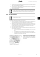
EMC cable clamps:
1. Loosen the screw in the EMC cable clamp.
2. Strip the cable jacket off in a length equal to the distance from the EMC cable
clamp to the terminal block in question, see illustration
Auxiliary Connection
Area
, arrow (1).
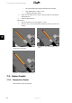
3. If shielded cable is used cut the cable shield approx. 10 mm and fix the cable
in the cable clamp as shown in the following illustrations:
7. Connection of Peripheral Units
L00410582-01_02 55
7