
Technical data

7. Connection of Peripheral Units
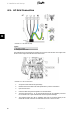
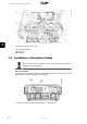
7.1. Overview
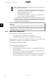
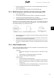
Auxiliary interfaces are provided via PELV circuits and are safe to touch during
normal operation. AC and PV must, however, be turned off before installation of
peripheral units.
Note:
For wiring details, refer to the section
Auxiliary Specifications
.
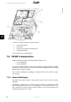
The inverter has the following auxiliary input/output:
Communication interfaces
• GSM modem
• RS485 communication (1)
• Ethernet communication (2):
- all TLX CN variants: service interface
- TLX CN Pro and TLX CN Pro+ variants only - Web Server functionality
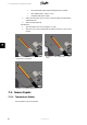
Sensor inputs (3)
• PT1000 temperature sensor input x 3
• Irradiation sensor input
• Energy meter (S0) input
Alarm Output (4)
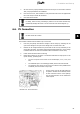
Except for the GSM modem, which has an externally mounted antenna, all auxiliary interfaces
are located internally in the inverter. For setup instructions, refer to the chapter
User Interface
,
or the Web Server User Manual.
7. Connection of Peripheral Units
L00410582-01_02 53
7