
Technical data
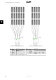

PV Cable Dimensions and Layout
As a rule of thumb the power loss in the PV cables should not exceed 1 % of nominal value in
order to avoid losses. For an array of 5000 W at 700 V, this corresponds to a maximum resist-
ance of 0.98 Ω. Assuming aluminium cable is used (4 mm
2
→ 4.8 Ω/km, 6 mm
2
→ 3.4 Ω / km),
the maximum length for a 4 mm
2
cable is approximately 200 m and for a 6 mm
2
cable approxi-
mately 300 m. The total length is defined as twice the physical distance between the inverter
and the PV array plus the length of the PV cables included in the modules. Avoid looping the DC
cables as they can act as an antenna of radio-noise caused by the inverter. Plus and minus ca-
bles should be placed side by side with as little space between them as possible. This also low-
ers the induced voltage in case of lightning and reduces the risk of damage.
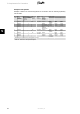
DC Max. 1000 V, 12 A
Cable length
4 mm
2
- 4.8 Ω /km
< 200 m*
Cable length
6 mm
2
- 3.4 Ω /km
>200-300 m*
*The distance between inverter and PV array and back, plus the summarised length of the ca-
bles used for PV array installation.
Table 5.6: Cable Specifications
5.3.1. Recommendations and Goals when Dimensioning
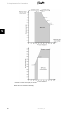
Optimising the PV Configuration: Voltage
The output power from the inverter can be optimised by applying as much ‘open circuit voltage’
as possible/allowed per input. However, the lowest ‘open circuit voltage’ should not be lower
than 500 V.
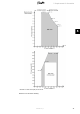
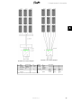
Examples:
1. In a PV system of 75 modules, each with an open circuit voltage of 40 V at -10°C and
1000 W/m², it is possible to connect up to 25 modules in one string (25 * 40 V = 1000
V). This allows for three strings and every string reaches the maximum inverter input
voltage of 1000 V at -10 °C and 1000 W/m
2
, similar to PV system examples 1 and 2.
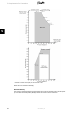
2. Another PV system only has 70 modules of the same type as above. Thus only two
strings can reach the optimum of 1000 V. The remaining 20 modules reach a voltage
value of 800 V at -10 °C . This string should then be connected to the last inverter
input, similar to PV system example 4.
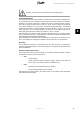
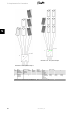
3. Finally, a third PV system has 62 modules of the type described above. With two
strings of 25 modules, 12 modules remain for the last inverter input. 12 modules only
produce 480 V open circuit voltage at -10 °C. The voltage at the last inverter input is
consequently too low. A correct solution is to connect 22 modules to the first inverter
input and two times 20 modules to the remaining two inputs. This corresponds to 880
V and 800 V at -10 °C and 1000 W/m
2
, similar to PV system example 4.
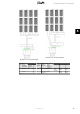
Optimising PV Power
The ratio between installed PV power at STC (P
STC
) and nominal inverter power (P
NOM
), the so-
called PV-to-grid ratio K
PV-AC
, is used to evaluate the sizing of the inverter. To reach a maximum
Performance Ratio with a cost efficient solution the following upper limits should not be excee-
ded.
5. Requirements for Connection
L00410582-01_02 39
5