
Technical data

Remember to switch off the PV load switch before correcting polarity!
PV to Earth Resistance
The monitoring of the PV to earth resistance is implemented for all countries as supplying ener-
gy to the grid with too low a resistance could be harmful to the inverter and/or the PV modules.
According to the German VDE0126-1-1 standard, the minimum resistance between the termi-
nals of the PV arrays and earth must be 1 kΩ / V
OC
, thus for a 1000 V system this corresponds
to a minimum resistance of 1 MΩ. However, PV modules designed according to the IEC61215
standard are only tested to a specific resistance of minimum 40 MΩ*m
2
. Therefore, for a 15 kW
power plant with a 10 % PV module efficiency, the total area of the modules yields 150 m
2
,
which again yields a minimum resistance of 40 MΩ*m
2
/ 150 m
2
= 267 kΩ.
The required limit of 1 MΩ has for that reason been lowered to 200 kΩ (+ 200 kΩ to compen-
sate for measuring inaccuracy), with the approval of the authorities (Deutsche Gesetzliche Un-
fallsversicherung, Fachhausschuss Elektrotechnik).
During installation, the resistance must be verified before connecting the PV modules to the in-
verter. The procedure for verifying the resistance is found in the section on
PV Connection
.
Grounding
It is not possible to ground any of the terminals of the PV arrays. However, it is compulsory to
ground all conductive materials, e.g. the mounting system to comply with the general codes for
electrical installations.
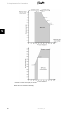
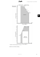
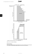
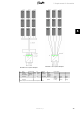
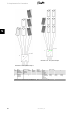
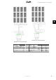
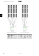
Parallel Connection of PV Arrays
The PV inputs of the inverter can be internally (or externally) connected in parallel. See below
for examples. The pros and cons by doing so are:
• Pros
- Layout flexibility
- Parallel connection makes it possible to apply a single two-wire cable from
the PV array to the inverter (reduces the installation cost)
• Cons
- Monitoring of each individual string is not possible
- String fuses/string diodes may be necessary
After making the physical connection, the inverter carries out an autotest of the configuration
and configures itself accordingly.
5. Requirements for Connection
L00410582-01_02 33
5