
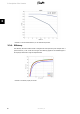
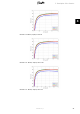
Technical data

5. Requirements for Connection
5.1. Pre-installation Guidelines
The aim of this section is to provide general information about the use of the TripleLynx CN
inverters.
The section should be read before designing the PV system. The section covers AC grid connec-
tion requirements, e.g. the choice of AC cable protection, the design of the PV system, e.g.
grounding, and finally the ambient conditions, e.g. ventilation.
5.2. Requirements for AC Connection
Always follow local rules and regulations.
Prevent the system from reconnecting by marking, closing or locking off the work
area. Unintentional reconnection may result in severe accidents.
Cover up all voltage-carrying system components that may cause personal injury
while working. Make sure that danger areas are clearly marked.
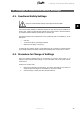
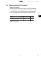
The inverters are designed with a three-phase, neutral and protective earth AC grid interface
for operation under the following conditions:
Parameter
Limits Min. Max.
Grid voltage, phase – neutral 230 V +/- 20 % 184 V 276 V
Grid frequency 50 Hz +/- 5 % 45 Hz 55 Hz
Table 5.1: AC Operating Conditions
When choosing grid code, the parameters in the above specification will be limited to comply
with the specific grid codes.
Earthing systems:
The inverters can operate on TN-S, TN-C, TN-C-S and TT systems.
Note:
Where an external RCMU is required in a TT system a 300 mA RCMU must be used in order
to avoid tripping. IT systems are not supported.
Note:
To avoid earth currents in the communication cable, ensure there is no difference in the
earthing potential of the different inverters when using TN-C earthing.
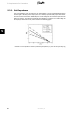
5.2.1. Mains Circuit Breaker, Cable Fuse and Load Switch
No consumer load should be applied between the mains circuit breaker and the inverter. An
overload of the cable may not be recognised by the cable fuse, see the section
Functional Over-
view
. Always use separate fuses for consumer load. Use dedicated circuit breakers with load
switch functionality for load switching. Threaded fuse elements like ‘Diazed’ and ‘Neozed’ are
not considered as a load switch. Fuse holder etc. may be damaged if dismounted under load.
Turn off the inverter by means of the PV load switch before removing/replacing the fuse ele-
ments.
5. Requirements for Connection
L00410582-01_02 25
5