
Technical data
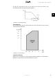
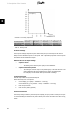

Illustration 3.6: Derating Temperature
TripleLynx CN 8 kW TripleLynx CN 10 kW TripleLynx CN 12.5 kW TripleLynx CN 15 kW
PV current, per input 12 A (+2 %) 12 A (+2 %) 12 A (+2 %) 12 A (+2 %)
Grid current, per phase 12 A (+2 %) 15 A (+2 %) 18 A (+2 %) 22 A (+2 %)
Grid power, total 8000 W (+3 %) 10000 W (+3 %) 12500 W (+3 %) 15000 W (+3 %)
To avoid unintentional derating due to measurement inaccuracy, the values in brackets are added to the limits.
Table 3.2: Derating Limits
PV Power Settings
The PV power settings comprise PV power and PV array area, for each input to the inverter.
Always set the installed PV power on the inputs. This is particularly important if the PV power
value differs for the individual PV inputs.
Determination of PV Input Settings
• Inputs in series
- The setting is the rated PV power (STC) for the installation.
• Inputs connected in parallel
- The setting for each PV input in the parallel group is the total amount of PV
power installed to that group divided by the number of parallel inputs.
For examples, see the section
Start-up and Check of Settings
.
Configure PV Inputs
Enter PV input values for asymmetrical layouts.
Access at security level 1 is required:
1.
In the display, go to [Setup → Calibration → PV array].
In the Web Server, go to [Inverter → Setup → Calibration → PV array].
2. Enter PV input values.
3. Enter PV array areas (optional).
Excessive Grid Power
The factory settings include a preset DC power capacity per input, which is 6 kW per PV input.
To avoid exceeding the maximum DC power allowed, the inverter will reduce the value evenly;
hence:
3. Description of the Inverter
18 L00410582-01_02
3