
Technical data
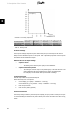

Fail Safe (Red LED flashing)
If the inverter detects an error in its circuits during the self-test (in connecting mode) or during
operation, the inverter goes into fail safe mode. The inverter will remain in fail safe mode until
PV power has been absent for a minimum of 10 minutes, or the inverter has been shut down
completely (AC + PV).
Refer to the section on
Troubleshooting
for further information.
3.3.3. International Inverter
Before connecting an inverter to the grid, obtain approval from the local distribution network
operator (DNO).
For initial selection of grid code refer to the section
Start-up and check of settings
.
View the current grid code setting
•
via the display at [Status → Inverter]
•
via the Web Server at [Inverter → Status → Inverter → General].
To change the grid code
• log on using security level 2 minimum
• select grid code
-
via the display at [Setup → Security]
-
via the Web Server at [Setup → Security]
Note:
To meet medium-voltage grid requirements, select a grid code ending in (MV).
For details of individual grid codes, contact Danfoss.
Selection of a grid code activates a series of settings as follows:
Grid power quality enhancement settings
• The cycle RMS values of the grid voltages are compared with two lower and
two upper trip settings, e.g. over voltage (stage 1). If the RMS values violates
the trip settings for more than the duration of "clearance time", the inverter
ceases to energise the grid.
• The cycle RMS value is averaged over 10 minutes. If this mean value exceeds
the trip setting, the inverter ceases to energise the grid.
Functional safety settings
• The cycle-to-cycle value of the grid frequency is also compared with two lim-
its: lower and upper. If the frequency violates the trip settings for more than
the duration of "clearance time", the inverters cease to energise the grid.
• Loss of Mains (LoM) is detected by two different algorithms:
1. Three-phase voltage surveillance (the inverter has individual control
of the three-phase currents). The cycle RMS values of the phase-
phase grid voltages are compared with a lower trip setting. If the
RMS values violate the trip settings for more than the duration of
"clearance time", the inverters cease to energise the grid.
3. Description of the Inverter
L00410582-01_02 15
3