
Technical data

3.3.2. Functional Safety
The inverters in the TripleLynx CN range are designed according to the German Functional
Safety VDE0126-1-1 (2006) standard.
Single Fault Immunity
The functional safety circuit is designed with two independent monitoring units, each having
control of a set of grid-separation relays to guarantee single fault immunity. All functional safety
circuits are tested during start-up to ensure safe operation for everyone. If a circuit fails more
than once out of three times during the self-test, the inverter goes into fail safe mode. If the
measured grid voltages, grid frequencies or residual current during normal operation differ too
much between the two independent circuits, the inverter ceases to energise the grid and re-
peats the self-test. The functional safety circuits are always activated and cannot be disabled.
Grid Surveillance
The grid is under constant surveillance when the inverter energises the grid. The following pa-
rameters are monitored:
• Grid voltage magnitude (instantaneous and 10-minute average)
• Grid voltage frequency
• Three-phase Loss-of-Mains (LoM) detection
• Rate-of-Change-of-Frequency (ROCOF)
• DC content of grid current
• Residual Current Monitoring Unit (RCMU)
The inverter ceases to energise the grid if one of the parameters violates the grid code. The
insulation resistance between the PV arrays and earth is also tested during the self-test. The
inverter will not energise the grid if the resistance is too low. It will then wait 10 minutes before
making a new attempt to energise the grid.
The inverter has four operation modes
For information on LEDs, refer to the chapter
User Interface
.
Off grid (LEDs off)
When no power has been delivered to the AC grid for more than 10 minutes, the inverter dis-
connects from the grid and shuts down. This is the normal night mode. The user and communi-
cation interfaces are still powered for communication purposes.
Connecting (Green LED flashing)
The inverter starts up when the PV input voltage reaches 250 V. The inverter performs a series
of internal self-tests, including PV auto detection and measurement of the resistance between
the PV arrays and earth. Meanwhile, it also monitors the grid parameters. When the grid pa-
rameters have been within the specifications for the required amount of time (depends on grid
code), the inverter starts to energise the grid.
On grid (Green LED on)
The inverter is connected to the grid and energises the grid. The inverter disconnects if: It de-
tects abnormal grid conditions (depending on grid code), if an internal event occurs or if no PV
power is available (no power is supplied to the grid for 10 minutes). It then goes into connect-
ing mode or off grid mode.
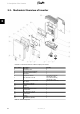
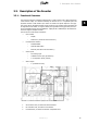
3. Description of the Inverter
14 L00410582-01_02
3