
Installation Guide

© Danfoss | Climate solutions | 2021.07
AN383426363919en-000101 | 9
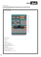
Panels with Gas Detection
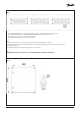
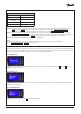
Gas Detector cable and sensor
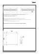
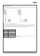
The gas detector remote sensor is supplied detached from the gas detection unit and must be connected after mounting. An M25
gland in the right side of the enclosure bottom plate is reserved for the remote sensor unit cable. Mount the remote sensor unit and
connect the cable as outlined in the final pages of the panel schematics.
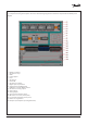
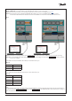
Gas Detector factory default settings – Modbus RTU
The PXE 02 and PXE 04 have variants that are equipped with Danfoss GDA gas detectors, cable and sensors. The gas detector unit
runs on a parallel Modbus RTU fieldbus system to the Evaporator Controllers and may be connected to the customers gas detector
Modbus RTU system via terminal X54 on the PXE 02 panels terminal X54 on the PXE 04 panels equipped with gas detection. The Gas
Detection Modbus RTU fieldbus network settings have the following default settings from the factory:
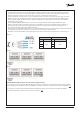
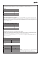
NOTE: The Slave ID can be changed but all other serial communication settings
cannot be changed.
Fig. 17
Table. 04
EKE 400 controller’s default comm settings
Slave ID 1
Baud rate 19.200 bps
Parity even
Data bits 8
Stop bit 1
Start bit 1