
Installation Guide

© Danfoss | Climate solutions | 2021.07
AN383426363919en-000101 | 7
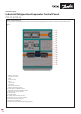
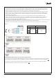
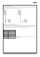
Step 05: Commence controller configuration. Start with either opening a previously configured file from the dropdown menu
FILE and choosing OPEN or start with configuring a new application by choosing the VALVE CONFIGURATION tab.
Other tabs and applications drawings will appear after making a choice in the VALVE CONFIGURATION tab.
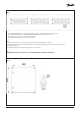
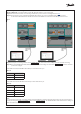
Step 06: Once satisfied with your controller configuration, you may write the configuration to the controller by choosing the
WRITE PARAMETERS TO EKE400 button at the top of the software window. Remember to save the different configurations
if required or export to Excel using the FILE dropdown menu in the top left corner of the software window.
Step 07: Repeat Step 04 to Step 06 until all controllers are configured.
Note:
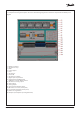
The CoolConfig software allows you to activate the IO for commissioning purposes which you may find useful.
See the I/O CONFIGURATION and ACTION tabs of CoolConfig.
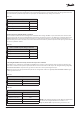
Table. 03
EKE 400 controller’s default comm settings
Baud rate 38.400 bps
Parity even
Data bits 8
Stop bit 1
Start bit 1
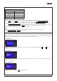
Quick startup – front door display
After powering up the panel navigating to the different controllers can be done via the front door display called the MMI. The MMI
display is an access point via CANbus (separate from and not affecting the Modbus RTU network) to the main status values of each
evaporator controller. Follow these steps to access information in the desired controllers:
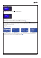
Step 02: Wait until the BIOS menu (see below) is shown on the screen and release the buttons. The current MCX selection will be
displayed in the upper right
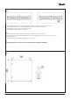
Fig. 11 MAIN screen
Fig. 12 BIOS screen
Step 03: Highlight and select (return ↵ button) “MCX SELECTION”
Fig. 13 MCX SELECTION
Step 01: From the “MAIN” screen the “BIOS” screen must be accessed. This is done by holding both the X and return ↵ buttons
simultaneously for 4–5 seconds