
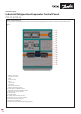
Installation Guide

© Danfoss | Climate solutions | 2021.07
AN383426363919en-000101 | 5
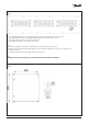
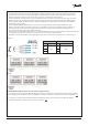
Fig. 07
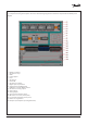
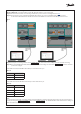
Fig. 08
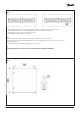
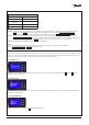
Fig. 09
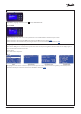
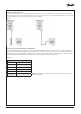
External wiring considerations: Power supply, Signal wiring and Fieldbus
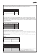
Available Modbus RTU parameters in each controller and gas detector
• 230 V cabling to and from the panel, the cable glands should be fed with Ø6-11 mm overall nominal diameter cable with
conductor areas 0.75-1.5 mm. For low voltage signal to and from the panel should be made with Ø6 mm overall nominal
diameter cables with conductor areas 0.75 mm. This is necessary in achieving the panel’s rated IP
• Unused cable gland openings must be closed, and all gland insert bores must be occupied to achieve the panel’s rated IP.
Gland insert bores may be plugged using the supplied sealing plugs. After removing unused cable from SKINTOP MULTI -
elastic gel will NOT SEAL, please use silicone to ensure proper IP. Note: non-punctured insert bores retain IP level 65/66
(depending on panel variant)
• The wiring of Modbus RTU (RS485) must be carried out in accordance with the standard ANSI/TIA/EIA-485-A-1998.
Galvanic separation shall be provided for segments crossing buildings. Common ground shall be used for all devices on
the same network inclusive router, gateways etc. All bus connections in the cables are made with twisted pair wires.
The recommended cable type for this is AWG 22/0.32 mm
•
The evaporator controllers and Gas Detector are on separate Modbus RTU networks and therefore have 2 separate panel terminals
• Connecting panels (evaporator controllers) in series via the correct terminals is shown in fig. 08
• Remember to terminate the RS485 network following the last physical device with a 120 ohm resistor, as shown in fig. 09
For a complete overview of all the available Modbus parameters for each evaporator controller device (there are 500+ Modbus
values available per controller) please refer to the EKE 400 controller datasheet for comprehensive descriptions and details:
Link
For a complete overview of all the available Gas Detector Modbus parameters please refer to the Gas Detector Modbus
Communication Guide for comprehensive descriptions and details: Link
EKE 400 Controllers GDA Gas detection unit
Panel terminal Panel terminal
D+
X107
D+
X54D- D-
GND GND