
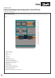
Installation Guide

© Danfoss | Climate solutions | 2021.07
AN383426363919en-000101 | 10
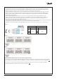
Gas Detector factory default settings – NH₃ PPM alarm settings
The gas detector will activate an alarm if there is an error detected or if there is a power failure to the unit. The gas detection units
also come with factory default 2-step alarm set-up ready for use. PPM alarm factory settings are as follows:
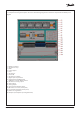
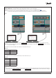
Gas Detector factory default settings - Terminals
The user interface enables the user to configure two individual alarm settings. ALARM 1 is a pre-alarm that, when activated, indi-
cates the gas level has passed a user-defined first threshold. If the gas level then passes a user-defined second threshold, the final
ALARM 2 (shutdown) is activated. For further information on setup of the gas detection unit via the display and information on
alarm schemes, please refer to the links to relevant documentation below. Factory default outputs from the panel gas detection unit
are, as factory default as follows:
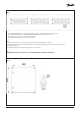
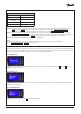
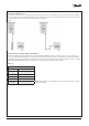
Connecting the Gas Detection safety circuit to the evaporator controllers
The default factory configurations of the PXE 02 and PXE 04 are not setup to output signals from the gas detector directly to the
inputs of the controllers in the panel. If required, the DO of a selected controller can be setup to de-energize following a High NH₃
PPM SHUTDOWN ALARM 2 output from the gas detection unit. This is done by following these steps:
Step 01: Locate the controller input terminal required to de-energize ALL its DO on a High NH₃ PPM SHUTDOWN ALARM 2 signal
from the gas detection unit.
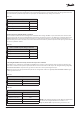
Table. 05
Table. 06
Table. 07
Table. 08
Gas Detector Factory Default Values
Description Default value
NH₃ PPM high level ALARM 1 25 PPM
NH₃ PPM high level ALARM 2 SHUTDOWN 35 PPM
NH₃ PPM range 0–100 PPM
PXE 02 and PXE 04 panels with gas detection
Description Default value
PPM High Level ALARM 1 (DO) X61
PPM High Level SHUTDOWN ALARM 2 (DO) X63
PPM level (4–20 mA AO) X54.1
PXE 02 panels
Description Gas Safety Circuit DI Terminal
EKE 400 Controller 1 X100
EKE 400 Controller 2 X400
PXE 04 panels
Description Gas Safety Circuit DI Terminal
EKE 400 Controller 1 X100
EKE 400 Controller 2 X200
EKE 400 Controller 3 X300
EKE 400 Controller 4 X400
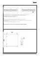
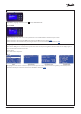
NOTE: In the following example, the Gas Detector in PXE 04 will
be wired to de-energize the DO from Controller 1 on a
High NH
₃
PPM ALARM 2 output from the gas detection unit