
Installation Guide

Installation guide
Industrial Refrigeration Evaporator Control Panels
PXE 02 & PXE 04
© Danfoss | Climate solutions | 2021.07
AN383426363919en-000101 | 1
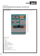
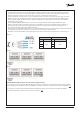
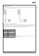
PXE 02: Component layout
For comprehensive wiring details please refer to the detailed wiring diagram that is delivered complete with the PXE 02 panels.
1. EKE 400 Controllers
2. Gas detector relays
3. MCBs
4. Power supplies
5. Fuses
6. Gas detector
7. Internal PE
8. Gas detector terminals
9. Digital input relay terminals
10. A) Gas detection RS485 terminal
B) EKE 400 controller’s RS485 terminals
11. Gas detection analog outputs
12. Analog inputs
13. Analog outputs
14. Optional motorized valve power
15. DIN rail for accessories (side of panel)
16. Fan and heater (side of panel)
17. Rail for wire organization
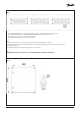
18. Baseplate (see baseplate layout diagram below)
Fig. 01