User Guide Monitoring unit Type PR-OCTO IoT Enabler for remote control and tracking of refrigeration equipment
User Guide | Monitoring unit, type PR-OCTO Content 1. 2. 3. 4. 5. 6. 7. 8. 9. 10. Introduction.......................................................................................................................................................................2 Layout ..................................................................................................................................................................................2 Compatibility...............................................
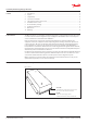
User Guide | Monitoring unit, type PR-OCTO Danfoss 80G8252 Fig. 2: Side B P Power supply connector: 100 – 240 V ~ Optional connector: the RS485/RS232 Ocommunication port for suitable thermostat. C COMM connector: the TTL communication port with the electronic thermostat. This is also the connector for the temperature probe inputs. Table 1: LED operation details RED LED OFF RED LED blinking RED LED ON RED LED fast blinking GREEN LED OFF GREEN LED fast blinking GREEN LED blinking 3.
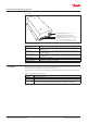
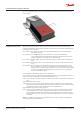
User Guide | Monitoring unit, type PR-OCTO 4. Connections and wires Fig. 3: Wiring details Danfoss 80G435 OCTO C Electronic Thermostat 100 – 240 V AC ~ COMM Cable This distance has to be at least 5 cm in case the power supply is not double insulated The PR-OCTO requires two connections, one for the power supply, the other with the electronic thermostat. The power supply must be shared with the electronic thermostat: the PR-OCTO must be powered on only when the thermostat is also powered on.
User Guide | Monitoring unit, type PR-OCTO 5. Choosing the position in the cooler The most important requirement for the OCTO installation is to find the location inside the cooler where the mobile network signal is stronger and the device protected.
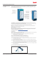
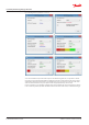
User Guide | Monitoring unit, type PR-OCTO Fig. 6: VBCTKSignalTester application screeeshots. a. b. c. d. e. f. Once discovered the best position with respect to the Antenna Signal Level, it is possible to decide if it is the case to protect the Side B (the one with the connectors) of the OCTO. To this aim, it can be adopted the same approach that the cooler manufacturer uses to protect the connector side of the electronic thermostat, hence a piece of plastic with an appropriate shape can be used.
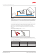
User Guide | Monitoring unit, type PR-OCTO Fig 7: In case of metallic protection, do not cross the indicated line otherwise the signal of the internal antenna results corrupted. OSS R OT C DO N OSS R OT C DO N 5 cm 6. Installation in the coolers During the industrial production of the coolers, there should be a phase in which the electronic thermostat is installed. In the same phase, also the OCTO device has to be installed.
User Guide | Monitoring unit, type PR-OCTO Fig. 8: Association between OCTO device and the specific cooler. 7. Prosa mandatory settings This section is to highlight the fundamental importance of the STEP 7 listed in Section 6. The association between the equipment and the PR-OCTO can be done: • Using the mobile app • With the Alsense Portal • or other modalities previously agreed with Danfoss (contact via e-mail: support.prosa@danfoss.com).
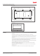
User Guide | Monitoring unit, type PR-OCTO Fig. 10: Top view 130.8 71.2 143.03 Danfoss 80G8255 78.2 4.7 11.5 26.6 +0.1 59.7 +0.25 Danfoss 80G8256 Fig. 11: Rear view 78.2 +0.25 10. Warnings • The installation of the PR-OCTO has to be performed only and exclusively by qualified and skilled technicians. • The installation of the PR-OCTO should be performed while the cooler is switched-off. • Inside the device there is a GPRS antenna.
ADAP-KOOL® © Danfoss | Climate Solutions | 2022.