
User`s guide

Installation
Installation
12a
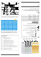
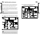
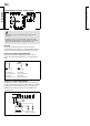
230 V a.c. connections - without safety thermostat
230 V a.c. connections - with safety thermostat
This circuit diagram is only valid if Danfoss actuators are used
The relays are to be connected as in the drawing without
safety thermostat.
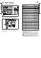
Electrical connections -
230 V a.c. - in general
Terminal Description Max. load
1 L Supply voltage 230 V a.c.
2 N Supply voltage 230 V a.c.
3 M1 Actuator - open, circuit I 0.2 A / 230 V a.c.
4 M1
Actuator - close, circuit I
alt. thermo actuator
0.2 A / 230 V a.c.
5
230 V a.c. supply voltage for M1,
circuit I
6 M2 Actuator - open, circuit II 0.2 A / 230 V a.c.
7 M2 Actuator - close, circuit II 0.2 A / 230 V a.c.
8
230 V a.c. supply voltage for M2,
circuit II
9 P1-1
Circulation pump I for heating,
circuit I
4 (2) A / 230 V a.c.
10
230 V a.c. supply for pump relay
R1
11 P2-1
Circulation pump II for heating,
circuit I
4 (2) A / 230 V a.c.
12
230 V a.c. supply for pump relay
R2
13 R3 Alarm relay 4 (2) A / 230 V a.c.
14
230 V a.c. supply for alarm relay
R3
25 P1-2
Circulation pump I for DHW,
circuit II
4 (2) A / 230 V a.c.
26
230 V a.c. supply for pump relay
R4
28 P2-2
Circulation pump II for DHW,
circuit II
4 (2) A / 230 V a.c.
29
230 V a.c. supply for pump relay
R5
Wire cross section: 0.75 - 1.5 mm
2
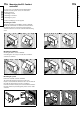
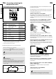
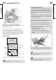
Electrical connections
Max. 2 x 1.5 mm
2
wires can be inserted into each screw terminal.
Incorrect connection can damage the TRIAC outputs. Max. load
(terminals 3, 4, (6 and 7)) 0.2 A / 230 V a.c.!
12b