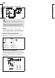
VI.JD.T2.02 2006.12 L66 ( ) Mixing and DHW controller www.danfoss.com ECL Comfort Installer's Guide www.danfoss.com *087R8172* *VIJDT202* VI.JD.T2.02 2006.
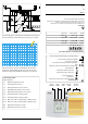
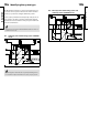
DHW flow temperature sensor, circuit II S6 DHW return temperature sensor, circuit II P1-1 Circulation pump 1, heating, circuit I P2-1 Circulation pump 2, heating, circuit I P1-2 ECA 73 / 80 / 86, circulation pump 1, DHW, circuit II P2-2 ECA 73 / 80 / 86, circulation pump 2, DHW, circuit II M1 Motorized control valve, circuit I M2 Motorized control valve, circuit II Adjust- Controller ment mode S5 Circuit Shift selector button Return temperature sensor, circuit I Circuit indicator S4 Contr
Table of Contents Sections in the Installer’s Guide The documentation for the ECL Comfort controller is composed of numbered sections. Only sections relevant to your ECL Comfort controller are included here. Before you start Installation 10 11 12 14 15 Identifying the system type Mounting the ECL Comfort controller Electrical connections 230 V a.c.
Before you start Sketch your application The ECL Comfort controller series is designed for a wide range of heating, domestic hot-water (DHW) and cooling systems with different configurations and capacities. If your system differs from the diagrams shown in section 10, you may want to make a sketch of the system about to be installed. This makes it easier to use the Installer’s Guide, which will guide you step-by-step from installation to final adjustments before the end-user takes over.
The ECL Comfort controller is a universal controller that can be used for various systems. Based on the shown standard systems, it is possible to configure additional systems. In this section you find the most frequently used systems. If your system is not quite as shown below, find the diagram which has the best resemblance with your system and make your own combinations. The functions can only be realized with ECL Comfort 301 and as of controller version 2.00. 10.
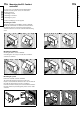
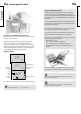
Mounting the ECL Comfort controller For easy access, you should mount the ECL Comfort controller near the system. Select one of the three following methods: • Mounting on a wall • Mounting on a DIN rail • Mounting in a panel Screws and rawlplugs are not supplied. Mounting on a wall Socket for mounting on wall: Order code No. 087B1149. Mount the terminal box on a wall with a smooth surface. Establish the electrical connections and position the controller in the box.
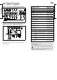
12a 12b Electrical connections 230 V a.c. - in general Terminal Description 1 L 2 N 3 M1 4 M1 5 6 M2 7 M2 8 9 P1-1 230 V a.c. connections - with safety thermostat 10 11 P2-1 12 13 R3 14 25 P1-2 26 28 P2-2 This circuit diagram is only valid if Danfoss actuators are used The relays are to be connected as in the drawing without safety thermostat. 29 Supply voltage 230 V a.c. Supply voltage 230 V a.c. Actuator - open, circuit I Actuator - close, circuit I alt. thermo actuator 230 V a.c.
14a 14b Connecting and placing the temperature sensors It is important that the sensors are mounted in the correct position in your system. The temperature sensor mentioned below are sensors used for the ECL Comfort 200 and 300 series which not all will be needed for your application! Outdoor temperature sensor (ESMT) The outdoor sensor should be mounted on that side of the building where it is less likely to be exposed to direct sunshine. It should not be placed close to doors, windows or air outlets.
14c Installation Installation Connecting the room panel / remote control The ECA 60 / 61 / 62 / 63 is activated by the setting in line 10 (section 32). The ECA 60 / 61 / 62 / 63 is powered by the system device bus which means that the bus must be active. The bus is activated by setting the controller address to 15 (section 32, line 199). Override For an active override, you have to choose the mode “scheduled operation”! Input S1 ...
15a 15b Inserting the ECL Card Installation The ECL Card contains factory settings for a standard system. If the actual system differs from the standard system, the controller must be adjusted accordingly. After the adjustment, the new settings should be stored on the ECL Card. For ECL Card copying and daily use including adjustment of temperatures and schedules, insert the ECL Card with the yellow side facing you.
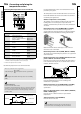
16 Adjusting the ECL Card settings 17 Setting the time and date line A General principles Actual time When the controller is connected and operating you can check and adjust all or some of the basic settings. Turn the ECL Card so that the grey side is facing you (see the example below). A 1035 Year 107 0222 Month, day Use the arrow buttons to move from line to line of the ECL Card, for example line 2: 1 ON 2 2 ON Use the shift button to switch between minutes, hours, years, months and days.
18 Monitoring temperatures and system units - line B Controlled units 1 B 1 2 2 ON ON Shift to manual mode. 3 ON Controlled units 1 B Flow temp. (S3) 65 30 ON 65 If the sensor is short-circuited, the display will indicate it as “- - -“. Basic set-up Controller mode 30 OFF or ON when The motorized actuator (gear motor) closes or opens the controlled unit as long as the relevant button is pushed. If pushed for more than 3 seconds, the actuator continues to close or open the valve.
20a 20b Setting the heat curve line C 1 ON C 1 2 2 3 Parallel displacement ON ON 15 Slope 0 Displacement Setting range Factory setting I -9 ... 9 K 0K If you want to adjust the parallel displacement of the heat curve, push the shift button. The symbol for the parallel displacement will blink. Slope Circuit Setting range Factory setting I 0.2 ... 3.4 1.5 Make your adjustments. The symbol for the slope of the heat curve will blink. Adjust the slope of the heat curve, if required.
21 Heating cut-out line 1 1 ON 1 1 1 2 2 1 ON ON 18 Setting range Factory setting I 10 ... 30 °C 18 °C Set the outdoor temperature limit at which you want the heating system to stop. 2 3 ON 40 90 Max. flow temp. The valve closes and after about 3 min. the heating circulation pump stops. The min. limitation set in line 2 will be ignored. 2 Flow temperature limits, min. and max. Circuit Setting range Factory setting I 10 ... 150 °C min. 10 , max.
23a 23b Room temperature influence line 3 B: Reference room temperature control This section is only relevant if you have installed a room temperature sensor or ECA 60 / ECA 61 / ECA 62 / ECA 63. 1 ON 1 2 3 ON ON Set a positive value for the min. influence and a negative value for the max. influence. Influence 3 Min. influence Used if your system is not equipped with thermostats and you select the room with room temperature sensor as a temperature reference for the rest of the rooms. 0 -40 Max.
26a 4 26b Control parameters lines 4-7 Proportional band, Xp 7 Neutral zone, Nz Circuit Setting range Factory setting Circuit Setting range Factory setting I / II 1 ... 250 K 80 / 80 K I / II 0 ... 9 K 3/3K Set the proportional band. A higher value will result in a stable but slow control of the flow temperature. Integration time constant, Tn Circuit Setting range Factory setting I / II 5 ... 999 sec. 30 / 20 sec.
29a Check list ✓ Is the ECL Comfort controller ready for use? Make sure that the correct power supply is connected to terminals 1 (Live) and 2 (Neutral). See section 12 or 13. Check that the required actuators, pumps, fans, dampers and burners are connected to the correct terminals. See sections 12 or 13. Check that all sensors are connected to the correct terminals. See section 14. Mount the controller and switch on the power. Insert the ECL Card with the yellow side facing you and push , if necessary.
30a ECL Card settings (circuit I) A Time and date Section 17 B System information Sections 18 & 19 C Heat curve Setting ranges 30b ECL Card settings (circuit II) Factory settings A Time and date Section 17 B System information Section 20 C Your settings Setting ranges Sections 18 & 19 Factory settings Your settings Slope 0.2 ... 3.4 1.5 See section 20 Parallel displacement -9 ... 9 K 0K See section 20 1 1 Limit for heating cut-out 10 ...
31a Service parameters (10-199) Circuit I (heating and cooling) Lines Setting ranges Factory settings Circuit I (heating and cooling) Lines Setting ranges Factory settings 141 Override input selection OFF / 1 ... 6 11 Setback temperature dependent on outdoor temperature OFF / -29 ... 10 °C -15 °C 142 Restart period, TR OFF / 1 ... 99 min. °C 12 Boost 0 ... 99% 0% % 0 min. min. 14 Optimizing time constant OFF / 10 ... 59 15 Adaptive function of room temperature OFF / 1 ...
32 Adjusting the service parameters In addition to the settings in line 1 to 7 on the grey side of the ECL Card, there is an extended service menu from line 10 and onwards. Push repeatedly to reach the lines numbered 10 and onwards. 0 Value 10 Line Range indicator Now you can move to any line of your choice. 32a Service parameter(s) 10-11 10 Choice of room panel / remote control Circuit Setting range Factory setting I 1 ... 2 1 Decides the communication with the room panel or remote control.
32b Service parameter(s) 12-13 12 Boost Circuit 32c Service parameter(s) 14-15 14 Optimizing time constant Setting range Factory setting I 0 ... 99% 0% Shortens the heating-up period by increasing the desired flow temperature by the percentage you set. Set the percentage at which you want the desired flow temperature increased temporarily. Circuit Setting range Factory setting I OFF / 10 ...
32d Service parameter(s) 17-20 17 Influence on desired flow temperature (Tflow.ref(I)) Circuit Setting range 21 Total stop Factory setting I OFF / 1 ... 20 K OFF The desired flow temperature in heating circuit I can be influenced by an external reference. OFF: The desired flow temperature in circuit I is not influenced by any other controller (slave). Circuit Setting range Factory setting I ON / OFF Decide whether you want a total stop during the setback temperature period. ON: 1 ...
32f Service parameter(s) 22-24 22 Pump exercise Circuit 30 Return temperature limitation Setting range Factory setting I / II ON / OFF OFF / OFF Exercises the pump to avoid blocking in periods without heat demand. ON: Setting range II 10 ... 110 °C 50 °C Set the return temperature you accept for the heating / DHW circuit. Set the acceptable return temperature limit.
32h Service parameter(s) 31-34 31 Return temperature limitation - upper limit (X-axis) Circuit Setting range Factory setting I -60 ... 20 °C 15 °C Set the outdoor temperature value (see drawing). 35 Return temperature influence - max. limitation Circuit Influence higher than 0: The desired flow temperature is increased, when the return temperature gets higher than the set limit. Factory setting I 10 ...
32j Service parameter(s) 36 Service parameter(s) 37 36 Return temperature influence - min. limitation Circuit Setting range Factory setting I / II -9.9 ... 0 ... 9.9 0.0 / 0.0 Set the influence from the return temperature on the desired flow temperature. Set the influence of the min. return temperature limitation (set in line 30 or lines 31-34). Influence higher than 0: The desired flow temperature is increased, when the return temperature gets below the set limit.
32l Service parameter(s) 43 43 Parallel operation of DHW and heating circuits Circuit Setting range Factory setting I OFF / 1 ... 99 K OFF Choose whether the heating circuit is to operate in dependence of the DHW circuit. 52 Closed valve / normal operation Circuit Setting range Factory setting I ON / OFF OFF The heating circuit can be closed when the controller acts as slave and when DHW charging is active in the master. OFF: Independent parallel operation, i.e.
32n Service parameter(s) 141 141 Override input selection Circuit Setting range 32o Service parameter(s) 142-153 142 Restart period, TR Factory setting I / II OFF / 1 ... 6 OFF / OFF Choose an unused temperature sensor input for overriding the schedule for circuit I and / or circuit II. The override can be activated for comfort or setback mode. For override the controller's mode must be in 'scheduled operation'! Circuit Setting range Factory setting I / II OFF / 1 ... 99 min. 20 / 20 min.
32p Service parameter(s) 145-153 Setting range Factory setting I / II 0.0 ... 23.9 16.1 / 16.1 The changeover time determines the moment when the activated pump stops and the deactivated pump starts. Circuit Setting range 197 LON reset Example: 16.1 the change will take place at 16:00 hours each day 20.3 the change will take place at 20:00 hours every third day 0.2 the change will take place at midnight every second day 8.0 the change will take place at 08:00 hours every tenth day.
32r Service parameter(s) 199 199 Master / slave address Circuit Setting range Factory setting I 0 ... 9, 15 15 The setting is relevant when more controllers are working in the same ECL Comfort system (connected via the system device bus (ECL Comfort BUS)). 0: The slave receives information about the outdoor temperature (S1), system time, and signal for DHW demand in the master. 1 ...
34a 34b Copying with the ECL Card Check the ECL Card and the software generations (see following example). Copy personal settings to additional controller(s) in identical systems Insert the ECL Card with the yellow side facing you. Ensure that the other controller(s) use(s) the same ECL Card type. (If this is not the case, please read section 15). Go to line 8 (is not displayed), which is the first line below line 7.
7a 7b Definitions Air duct temperature Humidity, relative Temperature measured in the air duct where the temperature is to be controlled. This value (stated in %) refers to the indoor moisture content compared to the max. moisture content. The relative humidity is measured by the ECA 62 / 63 and is used for the calculation of the dew point temperature. Balance temperature This setpoint is the basis for the flow / air duct temperature.
6a 6b Hot points The time shown in the display is one hour off? See the summer time changeover in line 198, section 32. The time shown in the display is not correct? The internal clock may have been reset, if there has been a power break for more than 12 hours. Set time and date. See section 17. The ECL Card is lost? Switch the power off and on again to see the system type and the software generation of the controller. Order a replacement from your Danfoss representative.
5a 5b Advantages of the ECL Card Save your personal settings to the ECL Card Go to line 9 (is not displayed), which is the second line below line 7. CPY 0 Card C99 Controller Restore ECL Card data After establishing your favorite temperatures, comfort periods etc., and after copying these to the ECL Card, you can set alternative settings. Insert the ECL Card and make the temporary settings, e.g. for holidays, but do not copy these.
4a 4b Set your personal schedule Monitor the current schedules Add an extra comfort period Select between lines 1-7 (Monday, Tuesday ...... Sunday) to see your individual schedules. Push the shift and + button simultaneously for 2 seconds. Changeover time Line Circuit Time line Periods with comfort temp. are shown as black bars Change the schedules Select appropriate day. The new period appears Adjust the new period.
2 Select circuit mode During scheduled operation (clock), the state indicator (a white arrow) will show you the control mode of the selected circuit. The white arrow will blink when this is a heating circuit and it is in the optimizing period. The mode can be set differently for each circuit by means of the function selector. However, if manual operation (hand) is chosen, this mode will apply to all circuits. Go to display C.
1a Choose your favorite display (circuit I) Choose the display - A, B, or C - for daily operations. Room temperature - display A Choose the display - A, B, or C - for daily operations. DHW temperature - display A Room temp. Line DHW temp. (S5) A Line Circuit 20 Outdoor temp. (S1) 1b Choose your favorite display (circuit II) A 56 Circuit 3 19 55 Desired room temp. Desired DHW temp.
1c Choose your favorite display (alarm) Choose the alarm settings by pushing the button until there is no circuit indication (display / lights). The ECL Comfort controller is designed by Danfoss for the automatic temperature control of heating, domestic hotwater (DHW), ventilation and cooling systems. Choose the display - A, B, or C - for daily operations. Some of the advantages of the ECL Comfort controller system are: • Secure control and the optimum use of energy resources.
Table of Contents Daily use Section 1 Choose your favorite display 2 Select circuit mode 3 Set your room and DHW temperature 4 Set your personal schedule 5 Advantages of the ECL Card 6 Hot points 7 Definitions The documentation for the ECL Comfort controller is composed of numbered sections. Only sections that are relevant to your ECL Comfort controller are included here. Installer's Guide: Grey sections 10 and onwards. Turn the guide over.