
Installation guide

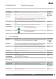


Menu selection Meaning Factory setting
REV.V. HOT WATER Indicates whether the exchange valve for hot water is located before or after the external
auxiliary heater. (Determines whether the external auxiliary heater may produce hot wa-
ter.)
INT / EXT
TOPH. AUX Indicates whether the external auxiliary heater can be used for anti-legionella. The ex-
change valve must be positioned after the external auxiliary heater.
/ ON
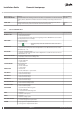
9.4 Sub-menu MANUAL TEST
Menu selection Meaning Factory setting
MANUAL TEST 0 = deactivate manual test
1 = activate manual test
2 = activate manual test with option of navigating from the SERVICE menu to check that
the temperatures rise for example.
-
HEAT PUMP 0 = stop heat pump
1 = start heat pump
N
The heat pump cannot be started in the event of an active
alarm.
-
BRINE PUMP 0 = stop the brine pump
1 = start the brine pump. If the value for Optimum is set to On the value can be control-
led between 30 – 100.
-
CIRC. PUMP 0 = stop the circulation pump
1 = start the circulation pump If the value for Optimum is set to On the value can be con-
trolled between 30 – 100.
-
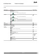
REV.V. HOT WATER 0 = heating mode for the exchange valve
1 = hot water mode for the exchange valve
-
SHUNT - = closes shunt
0 = shunt unaffected
+ = opens shunt
-
SYSTEM SHUNT Only at buffer tank
- = closes shunt
0 = shunt unaffected
+ = opens shunt
-
HGW-SHUNT - = closes shunt
0 = shunt unaffected+ = opens shunt
-
AUX. HEAT 1 0 = stop aux. heater step 1
1 = start aux. heater step 1
-
AUX. HEAT 2 0 = stop aux. heater step 2
1 = start aux. heater step 2
-
AUX. HEAT 3 0 = stop aux. heater step 3
1 = start aux. heater step 3
-
EXT.AUX.HEATER 0 = stop external auxiliary heater
1 = start external auxiliary heater
-
EXT.CIRC. PUMP 0 = stop circulation pump
1 = start circulation pump
-
SHUNT DEFR - = opens flow from defrosting tank
0 = shunt unaffected
+ = closes flow from defrosting tank
-
FAN L 0 = stop fan
1 = start fan at low speed
-
FAN H 0 = stop fan
1 = start fan at high speed
-
EXT. AUX. HEATER 0 = 0V on plinth 283
1 = control voltage 230V on plinth 283
-
ALARM 0 = stop signal on output External alarm
1 = start signal on output External alarm
-
VMGFQ202 Danfoss Heating Solutions
54
Installation Guide Domestic heat pumps