
Installation guide

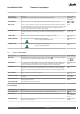


Menu selection Meaning Factory setting
START INTERVAL Minimum time interval between two heat pump starts in minutes. 20M(range:
10M / 30M)
ALARM BRINE Gives an alarm when the outgoing brine temperature falls below the set value.
(range: ,
-14°C / 10°C)
PRESS. PIPE Sensor on the compressor’s hot gas line. The value within brackets indicates maximum
permitted temperature. If this value is exceeded, the compressor will stop and start again
as soon as the temperature has dropped. No alarm shown in the display, however, a
square is shown in the left, lower corner of the display.
135°C
OUTDOOR STOP Displayed only if AIR is selected. Lowest outdoor temperature when the outdoor sensor
stops the compressor and heating or hot water are instead produced by the auxiliary
heater.
-20°C(range:
-20°C / -1°C)
SHUNT TIME Time in seconds. Indicates how often the shunt is to adjust its opening. 60S(range: 10S /
99S)
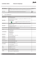
SHUNT COOLING The cooling shunt works towards the set temperature.
N
Does not apply to DHP-C Opti W/W.
18°C(range: 0°C /
30°C)
COOLING TEMP Set point value of the supply temperature at cooling mode.
N
Applies to DHP-C Opti W/W.
18°C(range: 5°C /
30°C)
9.3 Sub-menu AUX. HEATER
Menu selection Meaning Factory setting
MAX STEP
Maximum number of permitted steps for auxiliary heating. = no auxiliary heating per-
mitted (Means that only AUTO or HEAT PUMP can be selected).
2
(range: , 1, 2,
3, 4, 5, +4, +5)
INTEGRAL A2 Two conditions must be fulfilled in order to start the auxiliary heater: the integral’s value
to start must be less than integral A2, and the supply temperature must be 2°C lower
than the calculated temperature. See Service Instructions for more information.
-600(range: -50 /
-990)
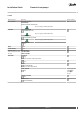
HYSTERESIS If the difference between the actual supply temperature and the calculated supply tem-
perature is too great (see Service Instructions for more information), either the integral
value is set to start value A2 (starts the auxiliary heater) or to 0 (stops the auxiliary heat-
er ).
20°C(range: 5°C /
30°C)
MAX CURRENT Refers to main fuse in the unit, in amperes. 20A(range: 16A /
35A)
HOT WATER STOP Stop temperature for hot water during AUX. HEATER. The value is read off by the hot wa-
ter sensor.
60°C(range:
50°C / 65°C)
DELAY AFTER EVU Time in minutes. Indicates how many minutes after EVU are to pass before the auxiliary
heater may be activated.
30M(range: 0M /
120M)
EXT.AUX.HEATER See table below for more information.
EXT.AUX.HEATER
Menu selection Meaning Factory setting
EXT.AUX.HEATER Indicates whether an external auxiliary heater is installed in the system.
/ ON
INTEGRAL A3 Indicates the value of the integral when external auxiliary heater is connected. -300(range:
-990 / INTEGRAL
A1 - 10)
TURN OFF DELAY Indicates how long the external auxiliary heater must continue to be active after its de-
mand is no longer needed.
0M(range: 0M /
180M)
Danfoss Heating Solutions VMGFQ202
53
Installation Guide Domestic heat pumps