
Installation guide


6.7 Selection of system solution and connection of external aux. heater
6.7.1 Introduction
N
Configure the heat pump for the desired system solution in the SERVICE\ADD. HEATER\EXTERNAL ADDITION
menu.
Also see section Piping installation.
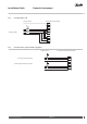
6.7.2 System solution 1
The heat pump is delivered configured for system solution 1.
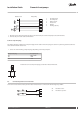
6.7.3 System solution 2
N
If necessary the external components must be fused using accessory 086U9685 FUSE TO EXTERNAL COMPO-
NENT according to the installation instructions supplied with the accessory. The tables below give the compo-
nents referred to.
For system solution 2, select the following in menu SERVICE\AUX. HEATER\EXT.AUX.HEATER:
▪
EXT.AUX.HEATER = ON
▪
REV.V. HOT WATER = INT
For DHP-H, DHP-H Opti, DHP-H Opti Pro/DHP-H Opti Pro +, DHP-C Opti the electrical connection for system solution 2 must be carried
out according to the following table:
Component Connection
Internal immersion heater I/O-card, output for 6 kW (normal connection)
External auxiliary heater I/O-card, output for 3 kW, connected and fused with 086U9685
Additional shunt Terminal block, 215/216
Internal exchange valve I/O-card, 214 (normal connection)
For DHP-L, DHP-L Opti, DHP-L Opti Pro/DHP-L Opti Pro + the electrical connection for system solution 2 must be carried out according to
the following table:
Component Connection
Internal immersion heater I/O-card, output for 6 kW (normal connection)
External auxiliary heater Terminal block 210, connected and fused with 086U9685
Additional shunt Terminal block, 215/216
Internal exchange valve I/O-card, 214 (normal connection)
For DHP-A Opti , the electrical connection for system solution 2 must be carried out according to the following table:
Component Connection
Internal immersion heater I/O-card, output for 3 kW and 6 kW as well as Defrost card, output for 6 kW (normal connections)
External auxiliary heater Defrost card; 283, connected and fused with 086U9685
VMGFQ202 Danfoss Heating Solutions
44
Installation Guide Domestic heat pumps