
Installation guide


6 Electrical Installation
Electrical voltage! The terminal blocks are live and can be highly dangerous due to the risk of electric shock.
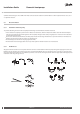
All power supplies must be isolated before electrical installation is started. The heat pump is connected inter-
nally at the factory, for this reason electrical installation consists mainly of the connection of the power sup-
ply.
Electrical installation may only be carried out by an authorized electrician and must follow applicable local
and national regulations.
The electrical installation must be carried out using permanently routed cables. It must be possible to isolate
the power supply using an all-pole circuit breaker with a minimum contact gap of 3 mm. (The maximum load
for externally connected units is 2A).
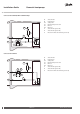
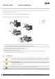
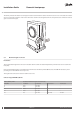
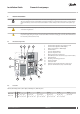
6.1 Electrical components
1 2 3
5
7
4
11 12
13
14
10
8
9
15
1 Terminal block (applies to the expansion card)
2 Terminal block (applies to DHP-A Opti)
3 Defrost card (applies to DHP-A Opti)
4 Terminal block
5 Space for Danfoss Online
7 Space for expansion card
8 Motor protection for compressor
9 230V/24V protective transformer (only certain models)
10 Automatic fuses
11 Resetting overheating protection
12 Control computer
13 Soft starter card
14 Capacitor (only models with 230 V compressor)
15 Space for Terminal block (only certain models)
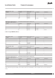
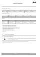
6.2 Fuse size
DHP-H, DHP-H Opti, DHP-L, DHP-L Opti, DHP-H Opti Pro, DHP-L Opti Pro
4 kW 6 kW 8 kW 10 kW 12 kW 16 kW
400V, 3-N A
16
1,8
/20
2,8
/25
3,8
10
1
/16
2
/20
3
10
1
/16
2
/20
3
16
1
/16
2
/20
3
16
1
/20
2
/25
3
20
1
/25
2
/25
3
230V, 1-N A
16
9
+10
1
/16
2
/25
3
16
9
+10
1
/16
2
/25
3
20
9
+10
1
/16
2
/25
3
25
9
+10
1
/16
2
/25
3
32
9
+10
1
/16
2
/25
3
-
Danfoss Heating Solutions VMGFQ202
39
Installation Guide Domestic heat pumps