
Installation guide


DHP-A Opti
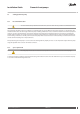
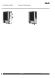
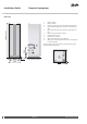
1845 (±10)
455
596
528
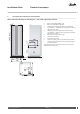
258
250
300
40±10
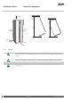
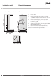
1
2
610
80
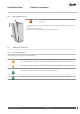
5
78
9
6
10
3
4
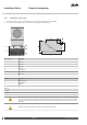
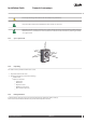
1 Brine in, 28 Cu
2 Brine out, 28 Cu
3 Lead-in for supply, sensor and communication cables
4 Heating system supply pipe, 22 Cu: 6-10 kW, 28 Cu: 12
kW
5 Heating system return pipe, 22 Cu: 6-10 kW, 28 Cu: 12
kW
6 Connection for bleed valve, 22 Cu
7 Hot water line, 22 mm
8 Cold water line, 22 mm
9 Expansion outlet brine circuit, R25 int.
10 Safety valve for temperature and pressure (only applies
to certain models)
The brine pipes can be connected on either the left or right-
hand side of the heat pump.
VMGFQ202 Danfoss Heating Solutions
20
Installation Guide Domestic heat pumps