
Installation guide

Installation Guide
Making Bump test on Danfoss gas detecting sensors,
types GDA and GDC
148R9544
148R9544
4 DKRCI.PI.S00.B2.02 / 520H2572 © Danfoss A/S (MWA), 2015-02 © Danfoss A/S (MWA), 2015-02 DKRCI.PI.S00.B2.02 / 520H2572 1
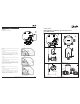
Beaker
EC/SC/CT-
Adaptor
Ampoules
M35
Adaptor
BUMP TEST equipment
EC/SC/CT-Adaptor Ampoule Breaker
Sensor PCB
Gas ows through
the back and
front of the
sensor head
Bump test on a wall mounted CO
2
detector
1
2
3
4
5
ENGLISH
Appendix 1
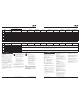
Checking the zero. (0.0 V output)
EC sensor
To adjust the zero, Pot VR201 must be operated. It is located on the
Sensor PCB
Connect a voltmeter to TP0 on the mother PCB and Con3, pin 3 on
the mother PCB
Pot VR201 (on the Sensor PCB) is used to adjust the zero of the
range (span). Measure the Voltage output between TP0 (negative)
and Con3 pin 3 (positive) at the 0V signal and adjust the Pot to 0.0
V or slightly positive (0.01 V is acceptable).
SC sensor
To adjust the zero, Pot RV2 must be operated. It is located on the
Sensor PCB.
Connect a voltmeter to TP0 on the mother PCB and Con3, pin 3 on
the mother PCB (see g. A1)
Pot RV2 (on the Sensor PCB) is used to adjust the zero of the range
(span). Measure the Voltage output between TP0 (negative) and
Con3 pin 3 (positive) at the 0V signal and adjust the Pot to 0.0 V or
slightly positive (0.01 V is acceptable).
CT sensor
To adjust the zero, Pot R3 must be operated. It is located on the
Sensor PCB.
Connect a voltmeter to TP0 on the mother PCB and Con3, pin 3 on
the mother PCB (see g. A1).
Pot R3 (on the Sensor PCB) is used to adjust the zero of the range
(span). Measure the Voltage output between TP0 (negative) and
Con3 pin 3 (positive) at the 0V signal and adjust the Pot to 0.0
V or slightly positive (0.01 V is acceptable).