
Datasheet
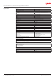
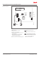
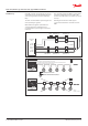
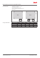
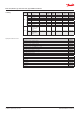

Electrical connection
12 4
Bus_B
Bus_A
0 V AC/DC
24 V AC/DC
Ackn. -/Test
button T1
X4
3
4
X8
X2
5
X9
Service Tool
Buzzer &
3-light alarm
X1
Analog Output
Status LED
Green/Yellow/Red
GND
JP5*
Open: 4-20mA
Closed: 2-10V AO_01
Jumper
J1
J2
J3
Sensor
Danfoss
148H119_11-2018
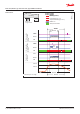
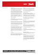
Status LED:
GREEN is power on.
- ashing if maintenance needed
YELLOW is an indicator of Error.
- when the sensor head is disconnected or not
the expected type
- AO is activated but nothing connected
- ashing when sensor is in special mode
(e.g. when changing parameters)
RED on alarm, similar to the buzzer & light alarm.
Ackn. -/Test button:
TEST - The button must be pressed
for 20 sec.
- Alarm1 and Alarm2 is simulated, stop on
release
ACKN. - Pressed while Alarm2, the audible
warning switches o and goes back on after
5 min. when the alarm situation is still active.
* JP4 open → AO 4-20 mA (Default)
JP4 closed → AO 2-10 Volt
Analog Output
Sensor
Ackn.-/Test
button T1
Open: 4 – 20mA
Closed: 2 – 10V
Status LED
Green/Yellow/Red
Jumper
Bus_B
Bus_A
X9
Service Tool
Buzzer &
3-light alarm
Data sheet | Danfoss gas detection units, types GD Basic and Basic+
AI272545693488en-000303 | 5
© Danfoss | DCS (ms) | 2019.10