
Datasheet

8 DKRCI.PD.S00.A4.02 / 520H2142 © Danfoss A/S (RC-MDP/MWA), 2014-04
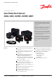
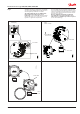
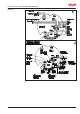
Gas Detection Sensor, type GDA, GDC, GDHC, GDHF, GDH
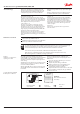
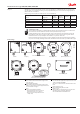
Functions - all models All GD models shown above have the same basic
functions. All settings are done by means of jumper
settings on the mother PCB.
See the section “Mother PCB” for more details.
For detailed information on how to adjust Alarm
setting - please see the instruction PI.S00.A.
Alarm
All GD models can detect 2 alarm levels and give
alarm via 2 volt free contacts. When an alarm has been
detected a yellow LED (Low Level Alarm) or a red LED
(High Level Alarm) will go ON. All GD sensors have
been preset by the factory, to realistic Low/High values
related to the actual ppm range of the GD model. The
actual Low and High Alarm ppm values can be read on
the external GD label.
The 2 volt free contacts can be set individually to either
Normally Open (NO) or Normally Closed (NC).
All GD models are factory set to NO
NO/NC can not be used as fail safe during
power failure.
Both Low and High Level Alarm can be delayed
individually before the 2 volt free contacts are
activated. This is useful when cross interference from
other gasses may occur. The delayed response time can
be set to 0, 1, 5 or 10 minutes.
All GD models are factory set to 0 minutes.
When the GD sensors have detected a Low or High
Level Alarm an option for having these alarms with
Manual reset or Auto Reset is possible. With the option
Manual reset selected, a push button on the mother
PCB must be activated to release the Low or High Level
Alarm.
With the option Auto reset selected, the release of the
Low or High Level Alarm is done automatically.
All GD models are factory set to Auto Reset.
The factory preset values can be adjusted, with a
voltmeter measuring a 0-5 V d.c output.
0 V corresponds to the min. ppm range (e.g. 0 ppm)
5 V corresponds to the max. ppm range (e.g. 1000)
Example:
If a setting of 350 ppm is required the voltage shall be
set to 1.75 V (35 % of 5 V)
Analog Output
All GD will continuously generate a linear analog
output, proportional to the gas concentration. The
signal is available as 4-20 mA, 0-10 V and 0-5 V.
All are available at the same time (see next page).
LCD display
The model with the LCD display will continuously
display the actual present ppm level in the room and
the Alarm messages.
Upper Line:
Actual present ppm level (e.g: “580 ppm”).
Lower Line:
Alarm status.
4 text messages are possible - only one at a time:
“No Alarm” Neither Low Level Alarm nor
High Level Alarm active.
“Lo Alarm on” Low Level Alarm active.
“Lo,Hi Alarm on” Both Low Level Alarm and
High Level Alarm active.
“Hi Alarm on” High Level Alarm active.
Normalization Period Once the GD is powered up it takes some time to
normalize. When GD is powered up it will give a
higher analog output (4-20 mA/0-10 V/0-5 V
1
)) in the
beginning and after some time it goes back
to the actual concentration (in clean air and no leaks,
the analog output will go back to:
~ 0 V/4 mA / ( ~ 0 ppm))
2
)
Times below are only intended as a guide.
They may vary due to temperature, humidity,
cleanliness of the air, storage time
3
) etc.
Model
EC Sensors are 2 min (all models)
SC Sensors are 60 minutes (all models)
CT Sensors are 60 minutes (all models)
IR Sensors are 2 minutes (all models)
1
)
Always use the voltage 0-10 V to check the output for
normalization check
2
)
GDC IR goes back to about 400 ppm as this is the normal
level in air. (~4.6 mA/~0.4 V/ 0.2 V)
3
)
If the GD has been in long-term storage or has been turned
off for a long period, normalisation would be much
slower. However within 1-2 hours the GD should have
dropped below the low alarm level and be operational.
The progress can be monitored exactly on the 0-10V
output. When the output settles around zero (400 ppm
in the case of IR CO
2
sensors) the GD is normalised. In
exceptional circumstances particularly with SC and CT
sensors the process can take up to 30 hours.
For SC Sensors, it must be calibrated at temperature of
operation.