
Installation guide


FP735SI
18
GB
3on 2on 2o1on 1oL N
Links to be made by installer
10 16 9 L N
Permanent links
Wiring Box - WC4B
1 23456789101112 13 14 15 16 L N
32
32
1 2 4
L 3N
COM CALL N
RET B
RM
T230
RET230
4 N 67
Brown Blue Orange Grey
Out In
HP22 2 Port Valve (Heating Zone 1)
Aux. Sw.
Motor
L N
L N 12
Perm L
N
Sw. L
Boiler *
HW
Zone 1
Zone 2
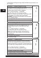
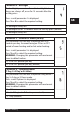
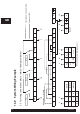
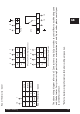
3.3 For wiring connections please refer to the diagram below:
12.0 System Wiring Example