
Specifications
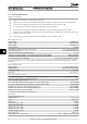


8.2 General Specifications
Protection and features
•
Electronic thermal motor protection against overload.
•
Temperature monitoring of the heatsink ensures that the frequency converter trips in case of overtemperature.
•
The frequency converter is protected against short-circuits between motor terminals U, V, W.
•
If a motor phase is missing, the frequency converter trips and issues an alarm.
•
If a mains phase is missing, the frequency converter trips or issues a warning (depending on the load).
•
Monitoring of the intermediate circuit voltage ensures that the frequency converter trips if the intermediate circuit
voltage is too low or too high.
•
The frequency converter is protected against earth faults on motor terminals U, V, W.
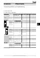
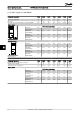
Mains supply (L1, L2, L3)
Supply voltage 200-240V ±10%
Supply voltage 380-480V ±10%
Supply voltage 525-600V ±10%
Supply frequency 50/60Hz
Max. imbalance temporary between mains phases 3.0% of rated supply voltage
True Power Factor (λ) ≥ 0.9 nominal at rated load
Displacement Power Factor (cosφ) near unity (> 0.98)
Switching on the input supply L1, L2, L3 (power-ups) enclosure frame H1-H5 Max. 2 times/min.
Switching on the input supply L1, L2, L3 (power-ups) enclosure frame H6-H8 Max. 1 time/min.
Environment according to EN 60664-1 overvoltage category III/pollution degree 2
The unit is suitable for use on a circuit capable of delivering not more than 100.000 RMS symmetrical Amperes, 240/480V
maximum.
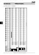
Motor output (U, V, W)
Output voltage 0 - 100% of supply voltage
Output frequency 0-200Hz (VVC+), 0-400Hz (u/f)
Switching on output Unlimited
Ramp times 0.05 - 3600 sec.
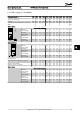
Cable lengths and cross sections
Max. motor cable length, screened/armoured (EMC correct installation)
See chapter EMC test results
Max. motor cable length, unscreened/unarmoured 50m
Max. cross section to motor, mains*
Cross section DC terminals for filter feedback on enclosure frame H1-H3 4mm
2
/11AWG
Cross section DC terminals for filter feedback on enclosure frame H4-H5 16mm
2
/6AWG
Maximum cross section to control terminals, rigid wire 2.5mm
2
/14AWG)
Maximum cross section to control terminals, flexible cable 2.5mm
2
/14AWG)
Minimum cross section to control terminals 0.05mm
2
/30AWG
*See tables for mains supply for more information
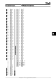
Digital inputs:
Programmable digital inputs 4
Terminal number 18, 19, 27, 29
Logic PNP or NPN
Voltage level 0-24V DC
Voltage level, logic '0' PNP < 5V DC
Voltage level, logic '1' PNP > 10V DC
Voltage level, logic '0' NPN > 19V DC
Voltage level, logic '1' NPN < 14V DC
Maximum voltage on input 28V DC
Input resistance, R
i
Approx. 4 k
Digital input 29 as thermistor input Fault: > 2.9kΩ and no fault: < 800Ω
General Specifications and ... VLT HVAC Basic Drive Design Guide
86 MG.18.C2.02 - VLT
®
is a registered Danfoss trademark
88