
Specifications


requests from another device, and how errors are detected
and reported. It also establishes a common format for the
layout and contents of message fields.
During communications over a Modbus RTU network, the
protocol determines:
How each controller learns its device address
Recognizes a message addressed to it
Determines which actions to take
Extracts any data or other information contained
in the message
If a reply is required, the controller constructs the reply
message and sends it.
Controllers communicate using a master-slave technique in
which only one device (the master) can initiate
transactions (called queries). The other devices (slaves)
respond by supplying the requested data to the master, or
by taking the action requested in the query.
The master can address individual slaves, or can initiate a
broadcast message to all slaves. Slaves return a message
(called a response) to queries that are addressed to them
individually. No responses are returned to broadcast
queries from the master. The Modbus RTU protocol
establishes the format for the master’s query by placing
into it the device (or broadcast) address, a function code
defining the requested action, any data to be sent, and an
error-checking field. The slave’s response message is also
constructed using Modbus protocol. It contains fields
confirming the action taken, any data to be returned, and
an error-checking field. If an error occurs in receipt of the
message, or if the slave is unable to perform the requested
action, the slave will construct an error message, and send
it in response, or a time-out occurs.
7.6.4
Frequency Converter with Modbus
RTU
The frequency converter communicates in Modbus RTU
format over the built-in RS-485 interface. Modbus RTU
provides access to the Control Word and Bus Reference of
the frequency converter.
The Control Word allows the Modbus master to control
several important functions of the frequency converter:
•
Start
•
Stop of the frequency converter in various ways:
Coast stop
Quick stop
DC Brake stop
Normal (ramp) stop
•
Reset after a fault trip
•
Run at a variety of preset speeds
•
Run in reverse
•
Change the active set-up
•
Control the frequency converter’s built-in relay
The Bus Reference is commonly used for speed control. It
is also possible to access the parameters, read their values,
and where possible, write values to them. This permits a
range of control options, including controlling the setpoint
of the frequency converter when its internal PI controller is
used.
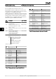
7.7 Network Configuration
To enable Modbus RTU on the frequency converter, set the
following parameters:
Parameter Setting
8-30 Protocol Modbus RTU
8-31 Address 1 - 247
8-32 Baud Rate 2400 - 115200
8-33 Parity / Stop
Bits
Even parity, 1 stop bit (default)
7.8 Modbus RTU Message Framing
Structure
7.8.1 Frequency Converter with Modbus
RTU
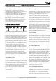
The controllers are set up to communicate on the Modbus
network using RTU (Remote Terminal Unit) mode, with
each byte in a message containing 2 4-bit hexadecimal
characters. The format for each byte is shown below.
Start
bit
Data byte Stop/
parity
Stop
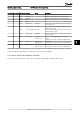
Coding System 8-bit binary, hexadecimal 0-9, A-F. 2
hexadecimal characters contained in each 8-
bit field of the message
Bits Per Byte 1 start bit
8 data bits, least significant bit sent first
1 bit for even/odd parity; no bit for no
parity
1 stop bit if parity is used; 2 bits if no parity
Error Check Field Cyclical Redundancy Check (CRC)
7.8.2 Modbus RTU Message Structure
The transmitting device places a Modbus RTU message
into a frame with a known beginning and ending point.
This allows receiving devices to begin at the start of the
message, read the address portion, determine which
RS-485 Installation and Set... VLT HVAC Basic Drive Design Guide
70 MG.18.C2.02 - VLT
®
is a registered Danfoss trademark
77