
Specifications

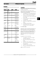


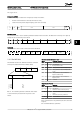


Closed Loop Set-up Wizard
No & Name Range Default Function
0-03 Regional Settings [0] International
[1] US
0
1-00 Configuration Mode [0] Open loop
[3] Closed loop
0 Change this parameter to Closed loop
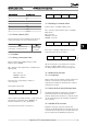
1-20 Motor Power 0.09-110kW Size related Enter motor power from nameplate data
1-22 Motor Voltage 50.0 - 1000.0V Size related Enter motor voltage from nameplate data
1-23 Motor Frequency 20.0 - 400.0Hz Size related Enter motor frequency from nameplate data
1-24 Motor Current 0.01 - 10000.00A Size related Enter motor current from nameplate data
1-25 Motor Nominal Speed 100.0 - 9999.0RPM Size related Enter motor nominal speed from nameplate data
4-12 Motor Speed Low Limit [Hz] 0.0 - Hz 0.0 Hz Enter the minimum limit for low speed
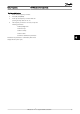
4-14 Motor Speed High Limit
[Hz]
0-Hz 65Hz
3-41 Ramp 1 Ramp up Time 0.05 - 3600.0 s 3
Ramp up time from 0 to rated 1-23 Motor Frequency
3-42 Ramp 1 Ramp Down Time 0.05 - 3600.0 s 3
Ramp down time form rated 1-23 Motor Frequency to 0
1-73 Flying Start [0] Disabled
[1] Enabled
0 Select Enable to enable the frequency converter to catch a spinning
motor. I.e. fan applications
3-02 Minimum Reference -4999-4999 0 The minimum reference is the lowest value obtainable by summing all
references
3-03 Maximum Reference -4999-4999 50 The maximum reference is the highest value obtainable by summing
all references
3-10 Preset Reference -100-100% 0 Enter the set point
6-29 Terminal 54 mode [0] Current
[1] Voltage
1 Select if terminal 54 is used for current- or voltage input
6-20 Terminal 54 Low Voltage 0-10V 0.07V Enter the voltage that corresponds to the low reference value
6-21 Terminal 54 High Voltage 0-10V 10V Enter the voltage that corresponds to the low high reference value
6-22 Terminal 54 Low Current 0-20mA 4 Enter the current that corresponds to the high reference value
6-23 Terminal 54 High Current 0-20mA 20 Enter the current that corresponds to the high reference value
6-24 Terminal 54 Low Ref./
Feedb. Value
-4999-4999 0 Enter the feedback value that corresponds to the voltage or current
set in 6-20 Terminal 54 Low Voltage/6-22 Terminal 54 Low Current
6-25 Terminal 54 High Ref./
Feedb. Value
-4999-4999 50 Enter the feedback value that corresponds to the voltage or current
set in 6-21 Terminal 54 High Voltage/6-23 Terminal 54 High Current
6-26 Terminal 54 Filter Time
Constant
0-10 s 0.01 Enter the filter time comstant
20-81 PI Normal/ Inverse Control [0] Normal
[1] Inverse
0
Select Normal [0] to set the process control to increase the output
speed when the process error is positive. Select Inverse [1] to reduce
the output speed.
20-83 PI Start Speed [Hz] 0-200Hz 0 Enter the motor speed to be attained as a start signal for
commencement of PI control
20-93 PI Proportional Gain 0-10 0.01 Enter the process controller proportional gain. Quick control is
obtained at high amplification. However if amplification is too great,
the process may become unstable
20-94 PI Integral Time 0.1-999.0 sec. 999.0 sec. Enter the process controller integral time. Obtain quick control through
a short integral time, though if the integral time is too short, the
process becomes unstable. An excessively long integral time disables
the integral action.
1-29 Automatic Motor Adaption
(AMA)
Off Performing an AMA optimizes motor performance
How to Programme VLT HVAC Basic Drive Design Guide
60 MG.18.C2.02 - VLT
®
is a registered Danfoss trademark
6
6