
Specifications
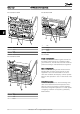
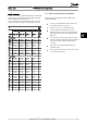
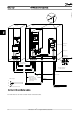
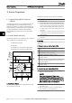
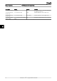
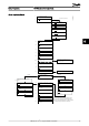

The FC 101 Start-up Wizard for Open Loop Applications
No & Name Range Default Function
0-03 Regional Settings [0] International
[1] US
0
0-06 Grid Type 0] 200-240V/50Hz/IT-grid
[1] 200-240V/50Hz/Delta
[2] 200-240V/50Hz
[10] 380-440V/50Hz/IT-grid
[11] 380-440V/50Hz/Delta
[12] 380-440V/50Hz
[20] 440-480V/50Hz/IT-grid
[21] 440-480V/50Hz/Delta
[22] 440-480V/50Hz
[30] 525-600V/50Hz/IT-grid
[31] 525-600V/50Hz/Delta
[32] 525-600V/50Hz
[100] 200-240V/60Hz/IT-grid
[101] 200-240V/60Hz/Delta
[102] 200-240V/60Hz
[110] 380-440V/60Hz/IT-grid
[111] 380-440V/60Hz/Delta
[112] 380-440V/60Hz
[120] 440-480V/60Hz/IT-grid
[121] 440-480V/60Hz/Delta
[122] 440-480V/60Hz
[130] 525-600V/60Hz/IT-grid
[131] 525-600V/60Hz/Delta
[132] 525-600V/60Hz
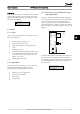
Size related
Select operating mode for restart upon
reconnection of the drive to mains voltage after
power down
1-20 Motor Power 0.12-110kW/0.16-150hp Size related Enter motor power from nameplate data
1-22 Motor Voltage 50.0 - 1000.0V Size related Enter motor voltage from nameplate data
1-23 Motor Frequency 20.0 - 400.0Hz Size related Enter motor frequency from nameplate data
1-24 Motor Current 0.01 - 10000.00A Size related Enter motor current from nameplate data
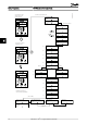
1-25 Motor Nominal
Speed
100.0 - 9999.0 RPM Size related Enter motor nominal speed from nameplate data
4-12 Motor Speed Low
Limit [Hz]
0.0 - 400 Hz 0 Hz Enter the minimum limit for low speed
4-14 Motor Speed High
Limit [Hz]
0.0 - 400 Hz 65 Hz Enter the maximum limit for high speed
3-41 Ramp 1 Ramp up
Time
0.05 - 3600.0 s Size related
Ramp up time from 0 to rated 1-23 Motor
Frequency
3-42 Ramp 1 Ramp
Down Time
0.05 - 3600.0 s Size related
Ramp down time from rated 1-23 Motor Frequency
to 0
1-73 Flying Start [0] Disabled
[1] Enabled
0 Select Enable to enable the frequency converter to
catch a spinning motor i.e. fan applications
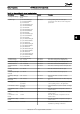
6-19 Terminal 53 mode [0] Current
[1] Voltage
1 Select if terminal 53 is used for current- or voltage
input
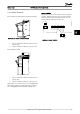
6-10 Terminal 53 Low
Voltage
0-10V 0.07V Enter the voltage that corresponds to the low
reference value
6-11 Terminal 53 High
Voltage
0-10V 10V Enter the voltage that corresponds to the high
reference value
6-12 Terminal 53 Low
Current
0-20mA 4 Enter the current that corresponds to the low
reference value
6-13 Terminal 53 High
Current
0-20mA 20 Enter the current that corresponds to the high
reference value
3-02 Minimum Reference -4999-4999 0 The minimum reference is the lowest value
obtainable by summing all references
How to Programme VLT HVAC Basic Drive Design Guide
MG.18.C2.02 - VLT
®
is a registered Danfoss trademark 57
6
6