
Specifications
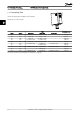
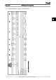
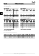
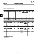

Enclosure
Power
[kW]
Height
[mm]
Width
[mm]
Depth
[mm]
Mounting hole
[mm]
Max. weight
Frame
IP
class
3x200-
240V
3x380-
480V
3x525-
600V
A
A incl
Decoupling
plate
a B b C d e f Kg
H6 20 15-18.5 30-45 22-30 518 595-635 495 239 200 242 - 8.5 15 24.5
H7 20 22-30 55-75 45-55 550 630-690 521 313 270 335 - 8.5 17 36
H8 20 37-45 90 75-90 660 800 631 375 330 335 - 8.5 17 51
H9 20 - - 2.2-7.5 268 374 257 130 110 205 11 5.5 9.0 6.6
H10 20 - - 11-15 399 419 380 165 140 248 12 6.8 7.9 12.0
I6 54 - 22-37 - 650 - 624 242 210 260 19 9.0 9.0 27.0
I7 54 - 45-55 - 680 - 648 308 272 310 19 9.0 9.8 45.0
I8 54 - 75-90 - 770 - 739 370 334 335 19 9.0 9.8 65.0
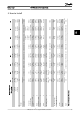
The above mentioned dimensions are only for the physical
units, but when installing in an application it is necessary
to add space for free air passage both above and below
the units. The amount of space for free air passage is listed
in the following table:
Enclosure Clearance needed for free air passage [mm]
Frame IP class Above unit Below unit
H6 20 200 200
H7 20 200 200
H8 20 225 225
H9 20 100 100
H10 20 200 200
I6 54 200 200
I7 54 200 200
I8 54 225 225
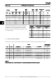
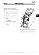
5.1.1 Side-by-Side Installation
The frequency converter can be mounted side-by-side and requires the clearance above and below for cooling.
Power Clearance above/
below (mm/inch)
Frame IP class 3x200-240V 3 x 380-480V 3 x 525-600V
H1 IP20 0.25-1.5kW/0.33-2Hp 0.37-1.5kW/0.5-2Hp 100/4
H2 IP20 2.2kW/3Hp 2.2-4kW/3-5.4Hp 100/4
H3 IP20 3.7kW/5Hp 5.5-7.5 kW/7.5-10 Hp 100/4
H4 IP20 5.5-7.5kW/7.5-10Hp 11-15kW/15-20Hp 100/4
H5 IP20 11kW/15 Hp 18.5-22kW/25-30Hp 100/4
H6 IP20 15-18.5Kw/20-25Hp 30-45kW/40-60Hp 22-30kW/30-40Hp 200/7.9
H7 IP20 22-30kW/30-40Hp 55-75kW/100-120Hp 45-55kW/60-100Hp 200/7.9
H8 IP20 37-45kW/50-60Hp 90kW/125Hp 75-90kW/120-125Hp 225/8.9
H9 IP20 2.2-7.5kW/3-10Hp 100/4
H10 IP20 11-15kW/15-20Hp 200/7.9
NOTE
With IP21/Nema Type1 option kit mounted, a distance of 50mm between the units is required.
How to Install VLT HVAC Basic Drive Design Guide
46 MG.18.C2.02 - VLT
®
is a registered Danfoss trademark
55