
Specifications
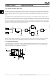
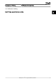
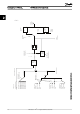
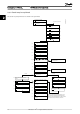

Closed Loop Set-up Wizard
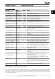
No & Name Range Default Function
0-03 Regional Settings [0] International
[1] US
0
1-00 Configuration Mode [0] Open loop
[3] Closed loop
0 Change this parameter to Closed loop
1-20 Motor Power 0.09-110kW Size related Enter motor power from nameplate data
1-22 Motor Voltage 50.0 - 1000.0V Size related Enter motor voltage from nameplate data
1-23 Motor Frequency 20.0 - 400.0Hz Size related Enter motor frequency from nameplate data
1-24 Motor Current 0.01 - 10000.00A Size related Enter motor current from nameplate data
1-25 Motor Nominal Speed 100.0 - 9999.0RPM Size related Enter motor nominal speed from nameplate data
4-12 Motor Speed Low Limit [Hz] 0.0 - Hz 0.0 Hz Enter the minimum limit for low speed
4-14 Motor Speed High Limit
[Hz]
0-Hz 65Hz
3-41 Ramp 1 Ramp up Time 0.05 - 3600.0 s Size related
Ramp up time from 0 to rated 1-23 Motor Frequency
3-42 Ramp 1 Ramp Down Time 0.05 - 3600.0 s Size related
Ramp down time from rated 1-23 Motor Frequency to 0
1-73 Flying Start [0] Disabled
[1] Enabled
0 Select Enable to enable the frequency converter to catch a spinning
motor. I.e. fan applications
3-02 Minimum Reference -4999-4999 0 The minimum reference is the lowest value obtainable by summing all
references
3-03 Maximum Reference -4999-4999 50 The maximum reference is the highest value obtainable by summing
all references
3-10 Preset Reference -100-100% 0 Enter the set point
6-29 Terminal 54 mode [0] Current
[1] Voltage
1 Select if terminal 54 is used for current- or voltage input
6-20 Terminal 54 Low Voltage 0-10V 0.07V Enter the voltage that corresponds to the low reference value
6-21 Terminal 54 High Voltage 0-10V 10V Enter the voltage that corresponds to the low high reference value
6-22 Terminal 54 Low Current 0-20mA 4 Enter the current that corresponds to the high reference value
6-23 Terminal 54 High Current 0-20mA 20 Enter the current that corresponds to the high reference value
6-24 Terminal 54 Low Ref./
Feedb. Value
-4999-4999 0 Enter the feedback value that corresponds to the voltage or current
set in 6-20 Terminal 54 Low Voltage/6-22 Terminal 54 Low Current
6-25 Terminal 54 High Ref./
Feedb. Value
-4999-4999 50 Enter the feedback value that corresponds to the voltage or current
set in 6-21 Terminal 54 High Voltage/6-23 Terminal 54 High Current
6-26 Terminal 54 Filter Time
Constant
0-10 s 0.01 Enter the filter time comstant
20-81 PI Normal/ Inverse Control [0] Normal
[1] Inverse
0
Select Normal [0] to set the process control to increase the output
speed when the process error is positive. Select Inverse [1] to reduce
the output speed.
20-83 PI Start Speed [Hz] 0-200Hz 0 Enter the motor speed to be attained as a start signal for
commencement of PI control
20-93 PI Proportional Gain 0-10 0.01 Enter the process controller proportional gain. Quick control is
obtained at high amplification. However if amplification is too great,
the process may become unstable
20-94 PI Integral Time 0.1-999.0 sec. 999.0 sec. Enter the process controller integral time. Obtain quick control through
a short integral time, though if the integral time is too short, the
process becomes unstable. An excessively long integral time disables
the integral action.
1-29 Automatic Motor Adaption
(AMA)
Off Performing an AMA optimizes motor performance
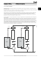
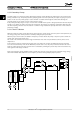
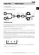
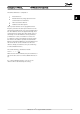
2.6.7 Tuning the Drive Closed Loop Controller
Once the frequency converter's Closed Loop Controller has been set up, the performance of the controller should be tested.
In many cases, its performance may be acceptable using the default values of 20-93 PI Proportional Gain and 20-94 PI Integral
Time. However, in some cases it may be helpful to optimize these parameter values to provide faster system response while
still controlling speed overshoot.
Introduction to VLT HVAC Ba... VLT HVAC Basic Drive Design Guide
MG.18.C2.02 - VLT
®
is a registered Danfoss trademark 29
2 2