
Specifications
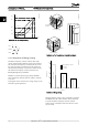
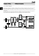
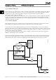

2.5.5 Example with Varying Flow over 1
Year
The example below is calculated on the basis of pump
characteristics obtained from a pump datasheet.
The result obtained shows energy savings in excess of 50%
at the given flow distribution over a year. The pay back
period depends on the price per kWh and price of
frequency converter. In this example it is less than a year
when compared with valves and constant speed.
Energy savings
P
shaft
=P
shaft output
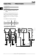
Flow distribution over 1 year
175HA209.11
60
50
40
30
20
10
H
s
0 100 200 300 400
(mwg)
B
C
A
750rpm
1050rpm
1350rpm
1650rpm
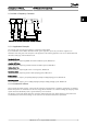
0
10
20
30
(kW)
40
50
60
200100 300
(m
3
/h)
(
m
3
/h)
400
750rpm
1050rpm
1350rpm
1650rpm
P
shaft
C
1
B
1
A
1
m
3
/
h
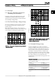
Distribution Valve regulation Frequency converter
control
% Hours Power Consumptio
n
Power Consumptio
n
A
1
-
B
1
kWh A
1
- C
1
kWh
350 5 438 42.5 18,615 42.5 18,615
300 15 1314 38.5 50,589 29.0 38,106
250 20 1752 35.0 61,320 18.5 32,412
200 20 1752 31.5 55,188 11.5 20,148
150 20 1752 28.0 49,056 6.5 11,388
100 20 1752 23.0 40,296 3.5 6,132
Σ
100 8760 275,064 26,801
2.5.6 Better Control
If a frequency converter is used for controlling the flow or
pressure of a system, improved control is obtained.
A frequency converter can vary the speed of the fan or
pump, thereby obtaining variable control of flow and
pressure.
Furthermore, a frequency converter can quickly adapt the
speed of the fan or pump to new flow or pressure
conditions in the system.
Simple control of process (Flow, Level or Pressure) utilizing
the built in PI control.
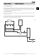
2.5.7
Star/Delta Starter or Soft-starter not
Required
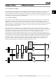
When larger motors are started, it is necessary in many
countries to use equipment that limits the start-up current.
In more traditional systems, a star/delta starter or soft-
starter is widely used. Such motor starters are not required
if a frequency converter is used.
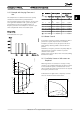
As illustrated in the figure below, a frequency converter
does not consume more than rated current.
Full load
% Full load current
& speed
500
100
0
0 12,5 25 37,5 50Hz
200
300
400
600
700
800
4
3
2
1
175HA227.10
Introduction to VLT HVAC Ba... VLT HVAC Basic Drive Design Guide
MG.18.C2.02 - VLT
®
is a registered Danfoss trademark 13
2 2