MAKING MODERN LIVING POSSIBLE Installation Guide ECtemp 535 Electronic Thermostat www.EH.danfoss.
ECtemp 535 Table of Contents 1 Introduction . . . . . . . . . . . . . . . 1.1 Technical Specifications . . . . . 1.2 Safety Instructions . . . . . . . . 3 4 6 2 Mounting Instructions 7 . . . . . . . . . 3 Settings . . . . . . . . . . . . . . . . . 11 4 Warranty . . . . . . . . . . . . . . . . . 15 5 Disposal Instruction 1 Introduction . . . . . . . . . . 16 ECtemp 535 is an electronic timer temperature controller, specially designed for floor heating systems.
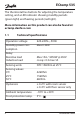
ECtemp 535 The thermostat has buttons for adjusting the temperature setting, and a LED indicator showing standby periods (green light) and heating periods (red light). More information on this product can also be found at: ectemp.danfoss.com 1.1 4 Technical Specifications Operation voltage 220-240V~, 50Hz Standby power consumption Max 0.30W Relay: Resistive load Inductive load Max 15A / 3450W @ 230V cos φ= 0.
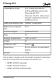
ECtemp 535 Temperature range 5-35°C with room sensor 5-45°C with floor sensor only Floor max 20-50°C Floor min 10-35°C, when installed with combination of room and floor sensor Cable specification max 1x4mm2 or 2x2,5mm2 Ball pressure temperature 75°C Pollution degree 2 (domestic use) Type 1C Storage temperature -20°C to +65°C IP class 31 Protection class Class II - Dimensions 85 x 85 x 54mm (in-wall depth: 24mm) Weight 107g The product complies with the EN/IEC Standard "Automatic electri
ECtemp 535 1.2 Safety Instructions Make sure the mains supply to the thermostat is turned off before installation. IMPORTANT: When the thermostat is used to control a floor heating element according to "Household and similar electrical appliances - Safety - EN/IEC 60335-1 : General requirements" and "EN/IEC 60335-2-96: Particular requirements for flexible sheet heating elements for room heating ", always use a floor sensor and never set the maximum floor temperature to more than 35°C.
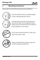
ECtemp 535 2 Mounting Instructions Please observe the following placement guidelines: Place the thermostat at a suitable height on the wall (typically 80-170cm.). The thermostat should not be placed in wet rooms. Place it in an adjacent room. Always place the thermostat according to local regulation on IP classes. Do not place the thermostat on the inner side of an exterior wall. Always install the thermostat at least 50 cm. from windows and doors.
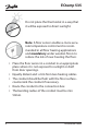
ECtemp 535 Do not place the thermostat in a way that it will be exposed to direct sunlight. Note: A floor sensor enables a more accurate temperature control and is recommended in all floor heating applications and mandatory under wooden floors to reduce the risk of over-heating the floor. ▪ Place the floor sensor in a conduit in an appropriate place where it is not exposed to sunlight or draft from door openings. ▪ Equally distant and >2cm from two heating cables.
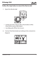
ECtemp 535 Follow the steps below to mount the thermostat: 1. Open the thermostat: devireg™550 D ▪ Gently press the release tab in the bottom of the thermostat using a flat object. ▪ Carefully pull off the front cover. 2. Connect the thermostat according to the connection diagram. N LOAD L L LOAD Mains Max. Load 220-240V~ 15 (1) A NTC Sensor N IP31 -10T30 D535 Installation Guide Standby maximum 0.
ECtemp 535 The screen of the heating cable must be connected to the earth conductor of the power supply cable by using a separate connector. Note: Always install the floor sensor in a conduit in the floor. 3. Mount and reassemble the thermostat. ▪ Fasten the thermostat to a socket or an exterior wall box by driving the screws through the holes in each side of the thermostat. ▪ Tighten the screws to fasten the thermostat. 4. Turn on the power supply.
ECtemp 535 3 Settings Sensor: How to specify whether an external floor sensor, the built-in room sensor or both is used to control the floor heating Note: The floor sensor option is selected by default. 1. Press the installation button D with a blade end. devireg™550 D 2. Press the • button. 3. Select one of the following options using the ▲▼ buttons: If only a floor sensor is used, choose: The built-in room sensor is not used.
ECtemp 535 If both a room sensor and a floor sensor is used, choose: This option is suitable for all rooms but wet rooms. The thermostat must be installed in the same room as the floor sensor and the heating elements. If only a room sensor is used, choose: This option is not recommendable due to an increased risk of overheating the floor. The thermostat must be installed in the same room as the heating elements. 4. To accept new selected sensor mode, press •. 5.
ECtemp 535 How to set the maximum floor temperature Special condition: This setting only applies if a floor sensor is used (the floor sensor or room/floor sensor option has been set). Note: The maximum floor temperature is set to 35°C by default. 1. To change the default temperature setting - press the • button. 2. Select the new temperature by using the ▲▼ buttons. 3. To accept the new selected temperature, press •. 4. Press installation button D to configure settings. devireg™550 D 5.
ECtemp 535 Note: Please contact the floor supplier before changing the maximum floor temperature and be aware of the following: ▪ The floor temperature is measured where the sensor is placed. ▪ The temperature of the bottom of a wooden floor can be up to 10 degrees higher than the top. ▪ Floor manufactures often specify the max temperature on the top surface of the floor (usually 27-28˚C). ▪ Always use a floor sensor or a room + floor sensor combination to control floor heating.
ECtemp 535 How to define the temperature scale Special condition: If floor sensor is selected, the numerical scale with steps from 1 - 6 must be selected. Note: By default, the Celsius scale is used. 1. To change the default temperature scale, press the • button. 2. Select a scale, use the ▲▼ buttons. You can choose between a numerical scale with steps from 1- 6 or the Celsius scale with steps from 5° - 45°. 3. To accept the selected temperature scale, press •. 4.
ECtemp 535 5 16 Disposal Instruction Installation Guide
ECtemp 535 Installation Guide 17
ECtemp 535 18 Installation Guide
ECtemp 535 Danfoss A/S Electric Heating Systems Ulvehavevej 61 7100 Vejle Denmark Phone:+45 7488 8500 Fax: +45 7488 8501 Email: EH@danfoss.com www.EH.danfoss.com Danfoss can accept no responsibility for possible errors in catalogues, brochures and other printed material. Danfoss reserves the right to alter its products without notice. This also applies to products already on order provided that such alterations can be made without subsequential changes being necessary in specifications already agreed.
Timer Thermostat Floor/Room Sensor 220-240V~ 50-60Hz~ +5 to +45°C 15A/3450W@230V~ IP 31 088L0042 ECtemp 535 ELKO 5 703466 151259 Designed in Denmark for Danfoss A/S Product Documentation