MAKING MODERN LIVING POSSIBLE DLX User Guide DLX 2.0 - DLX 2.9 - DLX 3.8 - DLX 4.
Danfoss can accept no responsibility for possible errors in catalogues, brochures and other printed material. Danfoss reserves the right to alter its products without notice. This also applies to products already on order provided that such alterations can be made without sub sequential changes being necessary in specifications already agreed. All trademarks in this material are property of the respective companies. Danfoss and the Danfoss logotype are registered trademarks of Danfoss A/S.
Contents 1. Introduction ................................................................. 4 2. Product Overview ........................................................ 5 2.1. Standards and Approvals ...................................................................................................................... 5 2.2. General Information ................................................................................................................................ 5 2.3. Symbols Used ................
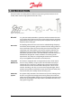
1. INTRODUCTION The DLX inverters are among the most efficient single phase grid-tied inverters on the market, which results in high yields from the solar array. Figure 1.1: PV system overview DC to AC In a grid-connected photovoltaic system the interface between the solar array and the utility grid consists of an inverter, which converts DC power produced from the solar array into AC power adapted to the voltage and frequency of the utility grid.
2. PRODUCT OVERVIEW This chapter gives an overview of the inverter with its supplied components, and how they are assembled. A brief explanation of how to unpack and handle the inverter safely is given, and symbols appearing both on the inverter and in this User Guide are explained. 2.1. Standards and Approvals DLX inverters are compatible with the following directives and safety standards: Table 2.
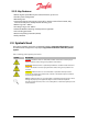
2.2.2. Key Features • World’s highest peak efficiency for isolated inverters; up to 97.3% • Flexible system configuration • Monitoring 24/7 • Internal data logger with storage capacity of 15 minutes intervals for one week, daily intervals for one year or weekly intervals for thirty years • MPPT range: 230 – 480 VDC • DC voltage range: 220 – 600 VDC • Automatic ON/OFF switching and temperature regulation • Anti-islanding protection • Reverse DC polarity protection (diodes) • Theft protection 2.3.
2.3.1. Labels The product label is attached to the lower right side of the inverter housing. It contains important identification parameters and characteristics for the inverter, and must be clearly visible after installation. Figure 2.3.1: Product label Table 2.2: Symbols appearing on the product label Symbol Description Symbol Description Discharge time 60 minutes: High voltages may be present inside the inverter for 1 hour after switch OFF.
2.4. Unpacking and Inspection Follow these instructions in this section to unpack and lift the inverter safely and to prevent injury and equipment damage. 2.4.1. Shipping Damage The DLX inverters are thoroughly checked and tested in accordance with international standards and approvals prior to dispatch. They are carefully packed before shipping. However, if any damage to the inverter is found when delivered, please provide feedback to your distributor immediately! 2.4.2.
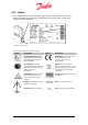
2.4.3. Unpacking Unpack the inverter as follows: • Place the box in position, with the top clearly visible and according to the arrow markings on the packaging. • Cut the seal, and open the box. • Take out the lock clip, the bag with accessories and the Installation Guide lying on the upper section of the foam packaging material. • Remove the upper part of the foam packaging material. • Both sides of the inverter case are narrowed in order to get a better grip on the device.
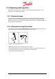
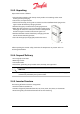
2.4.5.1. Mechanical Dimensions H: 610 mm W: 353 mm D: 158 mm Figure 2.4.3: Mechanical dimensions 2.4.5.2. Front Covers The front surface of the inverter consists of an upper and a lower cover. 1. Upper cover 2. Display 3. Lower cover; customer connection area 4. AC output 5. DC input 6. Network input Figure 2.4.4: Inverter structure The upper cover may only be removed by Danfoss authorized personnel.
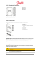
• Turn OFF the DC switch. DANGER Always disconnect the PV array cables from the inverter after turning the AC and DC OFF, but before removing the covers, as the PV array can supply up to 600 VDC to the inverter when exposed to sunlight. • Remove the four screws on the lower cover with a 4 mm hex key. • Take the cover off carefully. Figure 2.4.5: Lower cover • Store the lower cover and screws safely to avoid loss or damage. • Fasten the screws on the lower cover with a torque of 1.
3. SAFETY PRECAUTIONS This chapter contains instructions on how to install, operate and maintain the DLX inverters safely. These safety precautions must be read thoroughly and understood prior to the installation. Failure to follow the safety precautions may result in injury or death, and may void the warranty. 3.1.
3.1.2. Operation The inverter must only be operated in accordance with the information in this User Manual. NOTICE The DLX is a grid interactive inverter and must be used exclusively for its designed purpose, which is to convert PV-generated DC electricity into AC electricity to feed into the grid • The inverter must be operated in its original and technically intact condition without any unauthorized modifications.
3.2. Site Preparations Observe the following precautions when mounting and installing the DLX inverter on a suitable site. This is crucial to maintaining the efficiency of the inverter! 3.2.1. Mounting Sufficient ventilation and appropriate ambient temperatures are needed to prevent temperature build-up inside the inverter, which could lead to possible power losses.
3.2.2. Installation The installation of the inverter must be performed in accordance with the relevant local and national electrical regulations! DANGER Only persons who are qualified to install high voltage electrical equipment and are familiar with the electrical regulations applicable to the installation site may install the inverter.
3.3. Safety Equipment Required for Grid Connected Systems Ensure compliance with the local and national electrical regulations to satisfy the safety equipment requirements. NOTICE Safety equipment that meets the requirements for both the DC and AC operations must be provided and installed by the system installer in compliance with the local and national electrical regulations, and to prevent personal injury and protect the equipment. 3.3.1.
3.3.2.1. AC Fuses • AC fuses protect the supply conductors between the inverter and the utility grid. • AC fuses must be provided by the system installer. • Recommended rating for the AC fuses is as per the local and national electrical regulations. Table 3.2: Suggested AC current characteristics and fuse rating Inverter Model DLX DLX DLX DLX 2.0 2.9 3.8 4.6 Max AC Current Fuse Ratings Tripping Characteristics Type 10.5 A 15.2 A 19.7 A 23.0 A 13 A 20 A 25 A 25 A B or C Double Pole 3.3.3.
4. INSTALLATION This chapter describes how to install the inverter correctly, both mechanically and electrically, and details important issues related to the installation. This information is addressed to qualified persons, who are educated in installing high voltage electrical equipment and who follow the installation order as described in this User Manual.
4.2.1. Wall Bracket Depending on the mounting surface, different mounting methods may be required to secure the wall bracket. The system installer is responsible for selecting the correct type and number of fixings suitable to support the weight of the inverter on the mounting surface. • The bracket is designed to support 80 kg • The inverter must be mounted in a vertical orientation! • Mount the inverter in compliance with the minimum distances to ensure optimum cooling. Refer to 3.2.1. Mounting.
4.2.2. Inverter Attach the inverter to the mounting bracket as follows: • Locate the hooks for the carrier slots on the upper back of the inverter. • Locate the hooks for the steering slots on the lower back of the inverter. • Use the locating pin taps on the Stringbox. Figure 4.2.3: Hooks on the back of the inverter • Lift the inverter and guide the upper hooks into the slots on the bracket. • Align the lower hooks into the slots. • Slide the inverter onto the bracket. Figure 4.2.
• Ensure that the inverter is correctly aligned and secure in the bracket rails. • Using a 3 mm hex key, tighten the fixing clip with one screw into the inverter and one into the Stringbox (if present). • Recommended torque is 1.0 Nm Figure 4.2.5: Screws through the fixing clip • For theft protection: guide the lock clip through the fixing clip, and fasten with a padlock. • The padlock is not a part of the scope of supply. Figure 4.2.
4.3. Electrical Installation Correct electrical connection is critical for achieving a safe, long-term and reliable operation of the entire PV system. NOTICE The electrical connections on the AC and DC side must be performed by qualified persons and comply with local and national electrical regulations and the instructions detailed in this User Manual. Figure 4.3.1: Simplified PV system overview 4.3.1.
CAUTION The conductors must be listed for PV applications and the site environment and have the correct color coding to avoid material damage and bodily harm. • The insulation color-coding of electrical conductors must be understood in order to ensure safe and efficient installation, maintenance and repairs. Ensure compliance with the relevant local and national regulations. • Secure conductors so that they are kept away from objects that can damage the insulation (e.g. sharp edges). 4.3.2.
• The PV strings may be ungrounded, or grounded through either the negative or the positive string conductors. • The grounded DC conductors are connected to ground via the grounding strap. • The grounded conductors must be sized according to the local and national electrical regulations, and only carry current when electrical malfunctions occur. • Follow the safety instructions and specifications from the different PV module manufacturers regarding grounding requirements.
• The configuration of a positive grounded PV string differs from an ungrounded PV string by the connection of the cables to the DC terminal blocks and the addition of a grounding strap. • Array configuration depends on the module technology used. Both the positive and negative DC terminal blocks have three pairs of inputs, which allow three strings to be connected in parallel. Due to the inverter having one MPP-tracker the PV power should be identical for every string.
4.3.4.3. Stringbox Configurations The Stringbox is equipped with DC switch and SunClix connectors. P1, P2, P3: Positive connectors N1, N2, N3: Negative connectors Figure 4.3.8: DC connectors and DC switch P1, P2, P3: Terminals labeled 1.Ungrounded N1, N2, N3: Terminals labeled 2.Grounded N4: Grounded terminal N5: Terminal for the grounding strap P4: Ungrounded terminal DS: DC Switch Figure 4.3.
Negative Grounded PV String • The inverter is delivered from the factory in an ungrounded PV string configuration as standard. • Connect the grounding strap between N5 (fig. 4.3.9) and the DC ground receptacle labeled GND/PE in the inverter lower compartment. Figure 4.3.10: Negative grounded PV string Positive Grounded PV String • Connect the positive conductors (+) to the terminals labeled 2.Grounded, and the negative conductors (-) to the terminals labeled 1.Ungrounded.
• Conductor insulation rating must be higher where the backs of the modules cannot receive cooling or where the ambient temperature exceeds 40° C. Note the relevant national electrical regulations! • Follow the safety instructions and specifications from the module manufacturers regarding installation. String Connectors • The corresponding mating connectors must be provided by the system installer.
4.3.4.6. Jumper Position for the System Grounding Setup The jumper above the - NEG terminal in the customer connection area monitors the arrangement of the DC connection according to the system grounding setup. When delivered, the jumper is positioned in an ungrounded string configuration as standard. Depending on the grounding requirements from the module manufacturer the jumper must be pulled up and positioned correctly to match the required grounding of the PV strings.
The DLX series are single phase output inverters, which are designed so that they can be connected to a three-phase system. When several inverters are connected together, they must be distributed evenly between the grid phases. Single Phase Three Phase Figure 4.3.27: Example inverter AC connections Table 4.2: The different AC conductors Term (Abbr.) Description Phase conductor (L1/L2/L3) Neutral conductor (N) The ungrounded live conductors, which carry current to the load.
1. AC terminal block: GND: Ground terminal N: Neutral terminal (TN/TT) or Phase terminal (IT) L: Phase terminal 2. Cable gland • The current carrying conductors on the AC side must be rated for the current and have a cross section area of maximum 16 mm2 / 6 AWG. Ensure compliance with the relevant local and national electrical regulations! • The AC conductor resistance should be minimized by selecting as large a size of cable cross-section area as possible, up to 16 mm2 / 6 AWG.
4.3.6.1. Connection Procedures Figure 4.3.30: Customer connection area with network terminals 1. CAN bus terminal 2. RS-485 terminal 3. Ethernet connector 4. Network cable gland • Ethernet: Use CAT5e or better, with size 0.21 mm2 /24 AWG, and a maximum total length of 100 m. • CAN: Use CAT5e or better, with size 0.21 mm2 /24 AWG, with a maximum total length of 500 m. • RS-485 Use CAT5e or better, with size 0.
Plug the Ethernet cable directly in its port. The conductors must be connected to the same labeled terminals at both ends: i.e. H connected to H, L to L etc. Recommended tightening torque is 0.2 Nm The conductors must be connected to the same labeled terminals at both ends: i.e. A connected to A, B to B etc. Recommended tightening torque is 0.2 Nm. - Ethernet: - CAN: - RS-485: 6. Tighten the cable gland firmly.
Table 4.3: Position of the jumper for the termination resistance Network connection Jumper Position Pins The pins are terminated. The pins are disconnected. 1. CAN termination resistance 2. RS-485 termination resistance 4.3.7. Checks before Start Up Mounting: - Check that the bracket and the inverter are correctly mounted and secured. PV wiring: 34 - Check that the PV cables are rated for the PV current and for the expected environmental conditions.
CAUTION Verify that the lower cover is correctly secured so no moisture enters the housing and damages the electronic components.
5. START UP This chapter provides instructions to ensure a safe start- up of the DLX inverters. The startup of the inverter requires the presence of AC and DC voltages. Do not attempt to start up or commissioning the inverter if one of the voltage sources is not available. 5.1. How to Start Up A minimum available voltage of 184 VAC, 230 VDC and a DC power greater than 7 WDC is required before the inverter starts-up and begins feeding power to the grid. AC Side • Turn ON the AC circuit breaker(s).
2. RS-485 • Connecting all inverters via the RS-485 bus enables communication Danfoss comlynx compliant products. • Each inverter must be assigned an ID number, a bit rate number and a parity number manually: - The ID number must be between 1 and 247. Both the master inverter and the follower inverters need a bitrate number and a parity number. Compare with the setup in the third party equipment (eg. an external data logger) and write these numbers in the inverter’s network menu. Refer to section 6.2.4.2.
LEDs There are three LEDs next to the display screen. The upper one is red, the middle is yellow and the lower one is green. Table 0.1: LEDs. Symbol LED Function Action Red Malfunction! Inverter in shutdown mode Look for alarms in Active Alarms Green & Yellow Caution! Inverter still operates, but at a limited level Look for warnings in Active Alarms Green NONE Yellow Operates; inverter feeds power to the grid Inverter is OFF (Power < 7WDC) No action No action 5.2.3.
5.2.4. Software Installation At first power-up, and with sufficient AC power, the display shows the Start Installation screen. 1. Start Left – Cancel Right –Ok Enter – Confirm 2. Language Default – English Enter – Call up the list of languages Up or Down – Navigate through the list to find the preferred language: English, German, Spanish, French, Italian, etc.. Enter – Confirm Right – Next Enter – Confirm 3. Date DD.MM.
4. Time HH.MM (24 H) Enter – Call up the time Up – Increase present digit Down – Decrease present digit Right – Select next digit Left – Select previous digit Enter – Confirm Left – Back Right – Next Enter – Confirm NOTICE The time setting must match the time on the actual installation site, otherwise data may be overwritten! 5.
If the inverter is set to master, data must be collected from the follower inverters. The following screen is displayed: 7. Grid Configuration Enter – Call up the list of grid configurations Up or Down – Select the grid configuration of the actual installation site: TN/TT, IT, Undefined Enter – Confirm Left – Back Right – Next Enter – Confirm 8.
If the inverter is configured as master: step through and set the feeding phase (L1, L2, L3, L1-L2, L1-L3, or L2-L3 as required) for all follower inverters. 9. Plant Apparent Power Plant apparent power is used to determining certain VDE 4105 default settings. The value shown in the installation menu is a suggestion and must be confirmed. Please call up the digits and change values if required before pressing Enter.
CAUTION The selected grid code must match the actual installation site; otherwise the inverter may not operate or be compliant to relevant local and national regulations due to incorrect limit values. NOTICE • UK: Follow the local electrical regulations when selecting the grid code setting; either normal grid code setting or UK 16A Limit restricted grid code setting with a 16A limitation for G83 compliance.
11. Reactive Power Setting Enter – Call up the options Select the Reactive power setting: 1. For installations less than 13.8 kVA: VDE 4105 0 – 13.8 2. For installations greater than 13.8 kVA: VDE 4105 13.8 – Enter – Confirm Left – Back Right – Next Enter – Confirm 12. Screen Timeout Enter – Call up the digits Default – Screen backlight OFF after 60 sec Left – Back Right – Next Enter – Confirm NOTICE The smallest value to be set is 30 sec, and the highest is 99 sec.
Letter keyboard Number keyboard Table 5.2: Symbols appearing in the type screens Symbol Description Symbol Description Upper- or lower-case letter Confirm changes and exit the menu Point Clear the typing field Space Cancel last letter Go back without saving changes Go to the Letter keyboard Go to the Number keyboard • Enter must be pressed until the wanted letter/number/symbol is shown.
15. Unit Name Enter – Call up the keyboard The unit name helps to distinguish and identify specific inverters in a larger PV plant. Left – Back Right – Next Enter – Confirm 16. Message Enter – Call up the keyboard This message field is to help distinguish and identify specific inverters in a larger PV plant, or for any other information. Left – Back Right – Next Enter – Confirm 17. Owner Password Enter – Call up the digits Default: 0003.
NOTICE With several inverters connected it must be checked that the installation is carried out on all the follower inverters. • Look at the displayed menu and the LEDs: It is not carried out correctly if the installation menu is still displayed and/or the green LED is not lit and the yellow and red LEDs are lit.
5.3.1. Start The Self Test can only be activated when: • The installation procedure is executed • The country configuration is set to Italy • The inverter is in Running/Derating Mode (i.e. sufficient irradiation). Select: Commands > Inverter Commands > Self Test Left – Cancel Right – Ok Enter – Confirm The test needs some seconds to start. The test can fail if the irradiation is insufficient, as the inverter is unable to feed power to the grid. Restart the test later.
5.3.2. Voltage Monitoring First, the overvoltage monitoring is checked. The voltage trip level is ramped down from the maximum allowed voltage level, 276 VAC, and decreased until it equals the current grid voltage. The time it takes from equalization of the voltage to when the inverter disconnects from the grid is measured.
5.3.3. Frequency Monitoring The inverter repeats the test sequence, but now with the frequency trip limits. First, the upper frequency trip level is ramped down from the maximum allowed frequency level, and decreased until it equals the current grid frequency. The time it takes from equalization to disconnection is measured.
5.3.4. Finish After the test is successfully finalized, the test results are displayed. Enter Next to confirm each result, and enter Finish on the last result to finalize the test. 1. 2. 3. 4. • After successfully finalization of the test, the inverter goes back to the Inverter Command menu. • The test results are stored in Commands > Inverter Commands > Results Self Test. • If the test fails more than 3 times, contact Danfoss.
6. OPERATION This chapter describes how to operate the inverter via the LCD display with the function keys, or with a PC connected to the embedded webserver. Please refer to 5.2.2. for a description of the LCD Screen and the meanings of the colored LEDs 6.1. Access Levels and Passwords There are three access levels to the different submenus: Password Guest Owner Installer Access Read all values. Read all values and set all values except installer related values.
Lines: Number of highlighted lines indicates the current menu/submenu level, with the top line being the first level (Main Menu). • To activate the display when the screen saver is active (blank), press any key. 6.1.2. Home Home is the standard display, which is always shown if no buttons are touched within the screen timeout – interval, which is set during installation. (min 30 sec, max 90 sec). If the unit is set as master, the default menu contains status/mode information for the whole plant.
Up or Down – Navigate in the screen. Left or Right – Observe the daily, monthly and total yearly values of : • Energy harvest [Wh/kWh] • Peak power [Wp] • Earning [value of the respective country] • Avoided CO2 emission [kg]. Figure 6.2.4: Energy harvest throughout the day 6.1.2.1. Upper Display Area The left section shows the status of the inverter. Refer to Table 6.2 for the three different status options. It is also a shortcut to the Active Alarms. The middle section shows the operation mode.
Table 6.3: Inverter mode notifications Sign Mode LEDs Off: Input power is not sufficient to start the power control circuitry Yellow Sleeping: automatic shutdown.
Up or Down – Navigate through the submenus/values Enter – Select submenu/confirm Figure 6.2.7: Submenus to Status 6.1.3.1. Active Alarms Active Alarms displays detailed information about the current operating mode - and status signs appearing in the upper left corner of the Home screen. Refer also to 7.2. Table of Events. 6.1.3.2. Inverter Status Inverter Status displays the operating mode, status and operating parameters of the inverter.
Output Power Energy produced today Total feed-in power to the grid from all active inverters Total energy production throughout the day for the plant Phase Values Phase Values displays the inverter’s various feed-in parameters for the different grid phases.
Power Saving during night time Power saving can either be ON or OFF during nighttime. Enabling this option turns the GUI off 15 minutes after the inverter enters OFF mode, ie. night time, to save power. Only applicable for client inverters 6.1.4.2. Network Setup Network Setup displays the settings for the connected network, which can all be changed with the Owner password. Refer to 6.2. Connection between Inverter and Computer.
6.2.4.4. Plant Setup Plant Setup displays useful information about the PV plant, which can be changed using the Owner password.
Active Power Derating Active Power Derating displays limits related to active power according to the selected grid standard.
Grid Connect Grid Connect displays limits related to reconnection of the inverter according to the selected grid standard. Name VAC min connect VAC max connect fAC min connect fAC max connect Name of grid connect standard Minimum voltage for reconnection to grid Maximum voltage for reconnection to grid Minimum frequency for reconnection to grid Maximum frequency for reconnection to grid 6.2.4.6. Change the Country Settings • From the Main Menu: Select Setup >General Grid Setup > Grid Code.
6.2.5. Commands Commands give the ability to delete stored data in the inverter logger using the Owner password. Up or Down – Navigate through the submenus Enter – Select a submenu/confirm Figure 6.2.11: Submenus to Commands 6.2.5.1. Inverter Commands Inverter Commands gives the ability to delete events saved in the inverter data logger to provide storage space.
6.2.6. Alarm Setup Alarm Setup enables configuration of an email account, so the inverter can send information about energy production, status and operation mode to one or more receivers. Changes require use of the Owner password. Up or Down – Navigate through the submenus Enter – Select a submenu/confirm Figure 6.2.12: Submenus to Alarm Setup 6.2.6.1. Notification Setup In Notification Setup parameters needed for the inverter to send notifications about mode and status on e-mail must be typed in.
Procedure Go to the inverter menu Alarm Setup>Notification Setup. Fill out the text fields (Refer to 6.2.6.1. Notification Setup). • User Name and password: Usually provided by the Internet Service Provider. • Sender email address: This is the e-mail address appearing in the From - field when receiving mails from the inverter. It must be configured as follows: xxxxxx@xxxxxx.xxx. • Receiver 1 and 2: The recipients’ e-mail addresses. • SMTP server: The SMTP’s server address.
FTP Server Interval Notification time Group name Force send report dw.clxportal.danfoss.com Time interval of upload. Options are: none/hourly Reserved for future use Name of the group of inverters For testing ftp setup. Forces an upload of a report, irrelevant of schedule Note: Only an inverter configured as a master will upload FTP data. For third-party FTP services, an additional cost may be applied 6.2.7. Event Log Event Log displays information about inverter’s logged events.
6.2.8.1. Inverter Inverter displays a summary of the most important statistics of the inverter from today, the last month, the last year and in total since Start Up. Energy Earnings CO2 avoided Peak Power Inverter’s total energy production [kWh] Cash value of the feed-in energy in currency/kWh Avoided CO2 emissions [kg/kWh] compared to fossil fuel Inverter’s largest instantaneous amount of power production [W] 6.2.8.2.
6.3.1.1. IP Address The computer’s and the inverter’s IP address must be in the same range. If the inverter’s IP address is 192.168.10.X, the computer’s IP address must be 192.168.10.Y, where X and Y are different numbers between 1 and 254. Inverter The inverter’s default IP address is 192.168.10.20. To change the IP address, go to Setup>Network Setup and set the inverter’s IP address as required.
Connect the inverter and the PC to the router/switch with a regular Ethernet cable. 6.3.2.1. With DHCP – Dynamic IP Address Inverter 1. Go to Setup>Network Setup. 2. Set the IP address to 000.000.000.000. With this setting the router assigns a dynamic (DHCP) IP address automatically to the inverter. 3. Press OK. GUI will restart to configure the new network settings. 6.3.2.2. Without DHCP – Static IP Address Inverter 1. Go to Setup>Network Setup. 2.
3. When this is completed it should be possible to reach the DLX webserver by typing the external IP address of the local network or the web address (if a dynamic DNS service is used) in the computer’s web browser. 6.4. Internal Web Server The inverter has an internal, onboard web server providing detailed information about the operation, warning/alarms and energy production from the inverter/plant. • The web page is best viewed in Firefox 6.0 and Internet Explorer 8.0 or later versions.
6.4.2. Statistics Statistics gives a graphical overview over the energy production from the current week and the last 12 months. Figure 6.4.2: Statistics • PV plant: More detailed information for specific inverters in a plant can be found in the drop-down menu under Plant to the right. • More detailed values from the production data can be viewed by guiding the mouse button over the graphs.
6.4.3. Setup Setup gives different settings and information of every inverter in the PV plant. Figure 6.4.3: Setup • Plant Information shows important characteristics of every inverter in the PV plant. Model, serial number, revision and part no. information are all read-only. • General Settings shows date and time, CO2 - rating and rate and currency of the earning. Settings can be modified. • Alarm Setup shows information related to notifications and alarms from the inverter/plant.
6.4.4. Event Log Event Log shows information about events that the inverter has logged. The events are listed with the most recent event first. The information is read-only. Figure 6.4.4: Event Log • Recent events can be viewed by navigating directly to the different pages in the list on the bottom of the screen. • Events from previous months and years can be viewed by specific dates using the calendar to the left.
6.4.5. Status Status displays any warnings and alarms in the plant, and gives an overview of the plant’s technical characteristics and energy yield. The information is read-only. Figure 6.4.5: Status • Alarms tab identifies any specific warnings or alarms in the plant, with any activated items highlighted. The Extended Status lines are used by Danfoss service personnel to help diagnose possible faults.
7. TROUBLESHOOTING This chapter contains useful information if the inverter malfunctions during start-up or operation. Start by checking that the installation is carried out correctly, and then check the information in 7.2. Table of Events for possible solutions. If this does not help solve the problem, please contact the system installer. 7.1.
Display Message Grid fault (W/A – E05) Description No detection of the grid, not able to synchronize with the grid or fault within the country-settings GUI fault (W/A – E06) Display is not responding High voltage on input side (A – E07) Low voltage on input side (A – E08) DC voltage threshold of 600 VDC is exceeded DC voltage is too low to operate the inverter Low PV isolation resistance (W – E09) PV isolation resistance is below permitted level Failure on DC side (W/A – E10) Inverter failure on th
Display Message Low inverter temperature(W/A – E13) Current / power limitation (W/A – E14) Description Low internal inverter temperature PV power exceeds inverter rating Communication failure (A – E15) Internal communication failure Fan failure (W/A – E16) Internal air circulation has failed One or more fuses or circuit breakers are blown, or the jumper for the grounding setup is positioned incorrect Fuse fault (A – E17) Active power limitation (W/A – E18) Reactive power compensation (W/A – E19) Micr
Display Message High frequency on output side (W/A – E24) Description The frequency of the utility voltage is above the upper limit Low frequency on output side (W/A – E25) The frequency of the utility voltage is below the lower limit High output DC current (W/A – E26) Too high proportion of DC current in the grid feed Output current imbalance (W – E27) Imbalance in the output current between the phases (3 phase only) Fault ride-through Grid fault, still running (W – E28) VDR fault DC side (W – E29)
8. MAINTENANCE This chapter explains how to switch OFF and discharge the inverter safely. It also provides an overview of important regular maintenance procedures to ensure trouble-free operation of the DLX inverters. Finally, it is explained how to remove and return the inverters. 8.1.
8.2.1. Modules Maintain the PV modules as recommended from the manufacturer. 8.2.2. Cables Regularly check the cables inside and outside for signs of damage or overheating, i.e. warm conductors or surface corrosion. Replace frayed conductors immediately, find and fix the reason for the damage! 8.2.3. Electrical Connection Regularly check that the terminals and plugs are firmly tightened, and that the insulation is not deteriorated or corroded.
• Vacuum cleaner • Soft brush • Compressed air Figure 8.2.4: Heat sink cleaning 8.2.7. Fan The fan circulates the air inside the inverter, which distributes heat and thereby maintains the conversion capacity. The replacement of the fan requires removal of the inverter upper cover and must be performed by Danfoss authorized service personnel only! • A message is shown in the display when the fan needs replacement. Refer to 7.2. Table of Events.
Figure 8.2.5: Varistors on the DC side 8.2.9.2. AC Side • No alarms are raised regarding the condition of the varistors on the AC side. Therefore, they need to be checked regularly (at least once per year) or after lightning strikes. • Replace the damaged varistor with DLX Varistor Kit ordered from Danfoss, part number 139B0570. • The three varistors on the AC side are located in the right side of the connection area above the AC terminal area.
Figure 8.2.7: Checking the AC varistors Table 8.1: Measure if the varistors are damaged Measurements Between GND (1) and the left VDR (2) Between N (3) and the middle VDR (4) Between GND (3) and the right VDR(5) Undamaged 0Ω 0Ω 0Ω Replace ∞Ω ∞Ω ∞Ω Replacement Procedure • Use the service tool delivered in the packaging with the new varistors ordered from Danfoss. The service tool is designed as a fork, and can open up all terminal clamps simultaneously. Figure 0.
8.3. Replace Devices It is possible to add new inverters, or replace existing inverters, in a PV system. Follower • If the replaced inverter is a follower, the master inverter will automatically identify the replaced device and put it into operation. • The device number is automatically maintained. Master • If the replaced inverter is the master and master functionality is desired, an existing inverter needs to be set up as master. This is done in Setup>Network Setup>Set as Master unit.
9. WARRANTY The inverters are compatible with all relevant standards and are guaranteed to be free of defects from the date of purchase. Please refer to the Warranty documents on Danfoss’s web site www.Danfoss.com for more detailed information about the warranty of the inverter. If any questions, please contact your inverter supplier or the Danfoss office in your territory. 9.1. Warranty Service The standard warranty applies for 5 years after the date of installation, with an option for extension.
10. TECHNICAL DATA |S| P Q Vac,r Vac, min; Vac, max Iacmax Cosphi ac,r fr fmin, fmax Vdc,r Vmppmin Vmppmax Parameter AC DLX 2.0 Rated apparent power Rated active power @ cosphi = 1 Reactive power range Controlled power factor range Rated output voltage AC voltage range (P-N.
Danfoss Solar Inverters A/S Ulsnaes 1 DK-6300 Graasten Denmark Tel: +45 7488 1300 Fax: +45 7488 1301 E-mail: solar-inverters@danfoss.com www.danfoss.com/solar Danfoss can accept no responsibility for possible errors in catalogues, brochures and other printed material. Danfoss reserves the right to alter its products without notice. This also applies to products already on order provided that such alterations can be made without subsequential changes being necessary in specifications already agreed.