MAKING MODERN LIVING POSSIBLE DLX Installation Guide DLX 2.0 - DLX 2.9 - DLX 3.8 - DLX 4.
Danfoss can accept no responsibility for possible errors in catalogues, brochures and other printed material. Danfoss reserves the right to alter its products without notice. This also applies to products already on order provided that such alterations can be made without subsequent changes being necessary in specifications already agreed. All trademarks in this material are property of the respective companies. Danfoss and the Danfoss logotype are registered trademarks of Danfoss A/S. All rights reserved.
Contents 1. Product Overview ....................................................................................................... 4 1.1. Symbols Used ............................................................................................................................................ 4 1.2. Product Label ............................................................................................................................................. 4 2. Installation ....................................
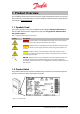
1. Product Overview This Installation Guide contains all the necessary install information to connect and start up the DLX inverter. The inverter must be used in compliance with the DLX User Guide, which is to be found at www.Danfoss.com. 1.1. Symbols Used The warning symbols used in this Installation Guide highlight important information on how to avoid shock hazards to equipment and persons. Pay particular attention when the symbols appear! Table 1.
Table 1.
1.3.2. Unpacking • Place the box in position, with the top clearly visible and according to the arrow marking on the packaging. • Cut the seal, and open the box. • Take out the lock clip, the bag with accessories and the Installation Guide lying on the upper section of the foam packaging material. • Remove the upper part of the foam packaging material. • Both sides of the inverter case are narrowed in order to get a better grip on the device.
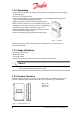
The front surface of the inverter consists of an upper and a lower cover. The upper cover may only be removed by Danfoss authorized personnel. Removal of the upper cover by unauthorized persons voids the warranty! The lower cover protects the connection area, and may be removed by the system installer for electrical connection and maintenance of the inverter. 1. Upper cover 2. User Interface 3. Lower cover; customer connection area 4. AC output 5. DC input 6. Network input Figure 1.3.
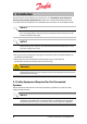
2. Installation The DLX inverters contain no user-serviceable parts, and installation and maintenance must be performed by qualified persons, who have a qualified knowledge of the local and national electrical regulations and who follow the instructions in this Installation Guide. NOTICE The DLX series is a grid interactive (grid-tie) inverter and must be used exclusively for its designed purpose, which is to convert PV-generated DC electricity into AC electricity to feed into the grid.
2.1.1. Disconnection Devices Disconnection devices, switches or circuit breakers, enable a shut-off from the power source during operation. They protect the current-carrying conductors and other system components from power surges and system malfunctions, and help to shut down the inverter safely for maintenance and repairs. • Both AC circuit breaker(s) and DC switch(es) are recommended to facilitate maintenance work and repairs of the inverter.
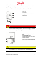
Avoid enclosed areas with poor air flow! Sufficient ventilation is needed to prevent temperature build up inside the inverter and hence possible power losses. Observe the minimum distances specified below to maintain optimal cooling: 1. 400 mm 2. 300 mm 3. 150 mm 4. 150 mm Figure 2.2.1: Minimum distances for optimum cooling For optimal operating conditions, the ambient temperature must be between -25° C & +65° C, and non-condensing relative humidity between 4 % and 99 %.
Figure 2.2.2: Inverter bracket Figure 2.2.3: Distances between fixing screws 1. Carrier slots for the inverter 2. Steering slots for the inverter 3. Carrier slots for the Stringbox 4. Fixing clip D1. 232.5 mm D2. 232.5 mm D3. 75 mm D4. 75 mm 2.2.2. Inverter Attach the inverter to the mounting bracket as follows: • Locate the hooks for the carrier slots on the upper back and the hooks for the steering slots on the lower back of the inverter. • Use the locating pins on the Stringbox. Figure 2.2.
• Lift the inverter up and guide the upper hooks into the slots on the bracket. • Control the lower hooks into the slots and slide the inverter onto the bracket. Figure 2.2.5: Mounting Inverter onto bracket • Ensure that the inverter is correctly mounted, and tighten the lock clip with one screw into the inverter and one into the Stringbox. • Apply a torque of 1.0 Nm 2.3.
Ensure that the conductors are listed for PV applications and the site environment, and that they have the correct color coding. 2.4. Electrical Installation Contact the local utility company for interconnection agreements and power approval before connecting to the grid. Correct electrical connection is critical for achieving a safe, long-term and reliable operation of the entire PV system.
2.4.2. Grounding Appropriate grounding of the entire PV system limits voltage surges, gives a common reference point for the conductive parts and facilitates the operation of the overcurrent devices. NOTICE • Grounding must be carried out by qualified persons only and comply with local and national electrical regulations. • Follow the safety instructions and specifications from the different PV module manufacturers regarding grounding requirements.
NOTICE Maximum Voltage: The open circuit voltage, VOC, must never exceed 600 VDC under any conditions. The voltage generated by PV modules is inversely proportional to the temperature; at lower temperatures the PV voltage increases from the nameplate rating and at higher temperatures the PV voltage decreases from the nameplate rating. NOTICE Ensure the DC switch in the Stringbox is in the OFF position, when removing the lower cover to access the connection terminals. 0 = OFF I = ON Figure 2.4.
P1, P2, P3: Ungrounded terminals N1, N2, N3: Grounded terminals N4: Grounded terminal N5: Terminal for the grounding strap P4: Ungrounded terminal DS: DC Switch Figure 2.4.6: Stringbox with DC switch Negative Grounded PV String • The inverter is delivered from the factory in an ungrounded PV string configuration as standard. • Connect the grounding strap between N5 in the Stringbox (fig. 2.4.6) and the DC ground receptacle labelled GND/PE in the inverter lower compartment. Figure 2.4.
Positive Grounded PV String • Connect the positive connectors (+) to the terminals labelled 2.Grounded and the negative connectors (-) to the terminals labelled 1.Ungrounded. • Switch the conductors connected to N4 and P4 (fig. 2.4.6). • Connect the grounding strap between N5 in the Stringbox (fig. 2.4.6) and the DC ground receptacle labelled GND/PE in the inverter lower compartment. Figure 2.4.8: Positive grounded PV string 2.4.3.2.
DANGER Be aware of high currents! If the DC terminals are mixed up during connection, high currents are generated in the conductors, which can pose shock hazards. Procedure • Turn OFF the DC switch(es) and the AC circuit breaker(s). DANGER The PV conductors are still charged after the DC switch in the Stringbox is turned OFF, due to power fed from the PV modules. Always turn OFF the remote DC switch and wait until the PV modules do not feed power. • Remove the PV connectors.
2.4.4. AC Connections (Grid) The AC connection includes wiring from the AC distribution panel through one or more circuit breakers to the AC terminal block of the inverter. Verify that the AC grid specifications are compatible with the inverter characteristics before connecting the inverter to the grid: • Single phase / Split phase • Voltage range (184 – 276 VAC) • Frequency range (50 Hz ±5 Hz) DANGER Turn OFF the AC circuit breaker before connecting the inverter to the AC grid to prevent electrocution.
2.4.4.1. Connection Procedures Figure 2.4.10: Connection area with AC terminals 1. AC terminal block: • GND: Ground terminal • N: Neutral terminal (TN/TT) or Phase terminal (IT) • L: Phase terminal 2. Cable gland • Use copper wire with a maximum cross-section area of 16 mm2 / 6 AWG. Ensure compliance with the relevant national electrical regulations! • The AC conductor resistance should be minimized. • Unscrew the cable gland locknut.
2.4.5. Network Connections The inverter is equipped with three communication interfaces: Ethernet, CAN, and RS-485. Ethernet provides communication between the integrated web server and a computer, either directly or via a router/switch. CAN allows communication between several DLX inverters. RS-485 allows communication with Danfoss compatible third party products or to Danfoss CLX products. 1. Follower inverter 2. Master inverter 3. CAN bus cable 4. Ethernet cable 5. RS-485 cable 6. Computer 7.
• Ethernet: Use CAT5e or better, with size 0.21 mm2 /24 AWG, with a maximum total length of 100 m. • CAN: Use CAT5e or better, with size 0.21 mm2 /24 AWG, with a maximum total length of 500 m. • RS-485: Use CAT5e or better, with size 0.21 mm2 /24 AWG, with a maximum total length of 1200 m • Unscrew the network cable gland, and take out the grommet. • Three-way cable gland insert: Figure 2.4.13: Insertion of the network cables in the cable gland 1.
CAN and RS-485 connection pinout CAN B(+) A(-) GND B(+) A(-) GND H L COMGND H L COMGND RS-485 2.4.5.2. Jumper Position for Termination Resistance With multiple inverters connected the jumper located behind the CAN / RS-485 terminal activates the termination resistance when the pins are terminated (short-circuited). This minimizes signal reflections in the cables and helps to avoids interference. • Single inverter: The two pins must be terminated (Default).
NOTICE Safety Equipment: The system installer is responsible for providing safety equipment that meets the requirements for both the DC and AC operations to protect the equipment and prevent personal injury. 2.6. Checks before Start Up Mounting: - Check that the bracket and the inverter are correctly mounted and secured. PV wiring: - Check that the PV cables are rated for the PV current and for the present environmental conditions.
3. Start Up A minimum available voltage of 184 VAC, 230 VDC and a power greater than 7 WDC is required before the inverter starts feeding power to the grid. AC side • Turn ON the AC circuit breaker(s). DC side • Turn ON the DC switch(es). 3.1. Initial Start When the inverter is started for the first time, an installation menu is automatically displayed to enable the configuration of certain critical values and operational settings. 3.1.1.
3.1.2. User Interface The User Interface on the front of the inverter contains a LCD screen, three LEDs and six function keys. Figure 3.1.1: Inverter user interface • To activate the display when the screen saver is active (blank), press any key. • With sufficient AC power the display shows the Start Up screen. 3.1.2.1. Function keys The function keys have the following uses: Table 3.
3.1.2.2. LED There are three LEDs next to the display screen. The upper one is red, the middle is yellow and the lower one is green. Table 3.2: LEDs. Symbol NONE LED Function Action Red Malfunction! Inverter in shutdown mode Look for alarms in Active Alarms Green & Yellow Caution! Inverter still operates, but at a limited level Look for warnings in Active Alarms Green Operates; inverter feeds power to the grid No action Yellow Inverter is OFF (Power < 7WDC) No action 3.1.2.3.
3.1.3. Start Installation configuration 1. Start Left – Cancel Right – OK Enter – Confirm 2. Language Selection Default – English Enter – Call up the list of languages Up or Down – Navigate through the list to find the preferred language; English, German, French, Spanish, Italian, etc.. Enter – Confirm Right – Next Enter – Confirm 3. Date DD.MM.
4. Time HH.MM (24 H) Enter – Call up the time Up – Increase present digit Down – Decrease present digit Right – Select next digit Left – Select previous digit Enter – Confirm Left – Back Right – Next Enter – Confirm NOTICE The time setting must match the time on the actual installation site, otherwise data may be overwritten! 5.
If the inverter is set to master, data must be collected from the follower inverters. The following screen is displayed: 7. Grid Configuration Enter – Call up the list of grid configurations Up or Down – Select the grid configuration of the actual installation site: TN/TT, IT, Undefined Enter – Confirm Left – Back Right – Next Enter – Confirm 8.
If the inverter is configured as master: step through and set phase values (L1, L2, L3, L1-L2, L1-L3, L2-L3) for all follower inverters. 9. Plant Apparent Power Plant apparent power is used to determining some VDE 4105 default settings. The value shown in the installation menu is a suggestion and must be confirmed. Please call up the digits and change value if required before pressing Enter.
CAUTION The selected grid code must match the actual installation site; otherwise the inverter may not operate or be compliant to relevant local and national regulations due to incorrect limit values. NOTICE • UK: Follow the local electrical regulations when selecting the grid code; either normal grid code setting or UK 16A Limit restricted grid code setting with a 16A limitation for G83 compliance.
12. Screen Timeout Enter – Call up the digits Default – Screen backlight OFF after 60 sec Left – Back Right – Next Enter – Confirm NOTICE The smallest value to be set is 30 sec, and the highest is 99 sec. Setting the value to 0 disables the screen timeout and leaves the screen backlight ON at all times. 13. Customer Name Enter – Call up the keyboard The keyboard enables the typing of a customer name.
Table 5.2: Symbols appearing in the type screens Symbol Description Symbol Description Upper- or lower-case letter Confirm changes and exit the menu Point Clear the typing field Space Go back without saving changes Cancel last letter Go to the Letter keyboard Go to the Number keyboard • Enter must be pressed until the wanted letter/number/symbol is shown.
16. Message Enter – Call up the keyboard This message field is to help distinguish and identify specific inverters in a larger PV plant, or for any other information. Left – Back Right – Next Enter – Confirm 17. Owner Password Enter – Call up the digits Default: 0003. Change the password to 4 optional digits Left – Back Right – Finish Enter – Confirm NOTICE With several inverters connected it must be checked that the installation is carried out on all the follower inverters.
Warning Box Errors: 1. No communication 2. Wrong grid settings • Check the LEDs on the inverters. If the yellow and red are lit check that the installation is correct performed and that the grid settings are correctly set. • If the ‘Start Installation’ screen is still shown, run through the installation process on the inverter. 3.2. Self Test for Italy The Self Test function is only valid for installation in Italy.
• • • • The inverter carries out four test sequences, all of which are displayed on the screen. After the test is finalized, each test result must be confirmed by entering Next. After entering Finish on the last result, the screen displays the Inverter Commands menu. The test results can be found in Commands>Inverter Commands>Results Self Test.
4. Connection between Inverter and PC The site performance can be checked remotely by using a computer. The connection can be achieved between the inverter and the computer either directly or via a network. 4.1. Without a Network To connect the inverter and the computer directly a regular Ethernet cable is needed. If the network card in the computer does not support Autosense, a crossover cable is needed to create a connection to the inverter. 1. Follower inverter 2. Master inverter 3. CAN bus cable 4.
5. Internal Web Server The inverter has an internal, onboard web Server providing detailed information about the operation, warning/alarms and energy production from the inverter/plant. • The web page is best viewed in Firefox 6.0 and Internet Explorer 8.0 or later versions. • From the web page certain inverter settings can be changed after applying the correct user name and password. • Type the inverter’s IP address in the computer’s web browser.
6. Troubleshooting This chapter contains useful information if the inverter malfunctions during start-up or operation. Start by checking that the installation is carried out correctly, and then check the information in section 4.2 for possible solutions. If this does not help solve the problem, please contact the system installer. 6.1.
Display Message Grid fault (W/A – E05) Description No detection of the grid, not able to synchronize with the grid or fault within the country-settings GUI fault (W/A – E06) Display is not responding High voltage on input side (A – E07) Low voltage on input side (A – E08) DC voltage threshold of 600 VDC is exceeded DC voltage is too low to operate the inverter Low PV isolation resistance (W – E09) PV isolation resistance is below permitted level Failure on DC side (W/A – E10) Inverter failure on th
Display Message Current / power limitation (W/A – E14) Description PV power exceeds inverter rating Communication failure (A – E15) Internal communication failure Fan failure (W/A – E16) Internal air circulation has failed One or more fuses or circuit breakers are blown, or the jumper for the grounding setup is positioned incorrect Fuse fault (A – E17) Active power limitation (W/A – E18) Reactive power compensation (W/A – E19) Microprocessor fault (W/A – E20) Ground current trip (A – E21) High AC vo
Display Message High frequency on output side (W/A – E24) Description The frequency of the utility voltage is above the upper limit Low frequency on output side (W/A – E25) The frequency of the utility voltage is below the lower limit High output DC current (W/A – E26) Too high proportion of DC current in the grid feed Output current imbalance (W – E27) Imbalance in the output current between the phases (3 phase only) Fault ride-through Grid fault, still running (W – E28) VDR fault DC side (W – E29)
7. Maintenance and Disposal Regular inspection of the PV system is an important safety precaution to ensure troublefree operation of the entire PV plant and the DLX inverter. Danfoss is committed to its policy of environmental responsibility, and therefore appeals to end users who are disposing of inverters to follow local environmental legislation and to seek safe and responsible means of disposal. 7.1.
8. Warranty The inverters are compatible with all relevant standards and are guaranteed to be free of defects from the date of purchase. 8.1. Warranty Disclaimer The warranty is void through misuse or when unauthorized repairs are performed on the inverter. The warranty does not cover normal wear and tear of the inverters or costs related to installation and troubleshooting of the electrical system. The warranty is only valid with an identifiable and accepted serial number. 8.1.1.
Installation Guide DLX series L00410622-01
9. Technical Data |S| P Q Vac,r Vac, min; Vac, max Iacmax Cosphi ac,r fr fmin, fmax Vdc,r Vmppmin Vmppmax Parameter AC DLX 2.0 Rated apparent power Rated active power @ cosphi = 1 Reactive power range Controlled power factor range Rated output voltage AC voltage range (P-N.
Danfoss Solar Inverters A/S Ulsnaes 1 DK-6300 Graasten Denmark Tel: +45 7488 1300 Fax: +45 7488 1301 E-mail: solar-inverters@danfoss.com www.solar-inverters.danfoss.com Danfoss can accept no responsibility for possible errors in catalogues, brochures and other printed material. Danfoss reserves the right to alter its products without notice.