
Specifications


8 – Service VMBMH302
3 Heat pump information
3.1 DHP-AX
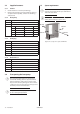
3.1.1 Dimensions and connections
The stand shown in the image is an accessory.
Figure 1: DHP-AX, dimensions and connections.
Position Name
1 Supply line heating system, DHP-AX 6, 8, 10: 22 Cu, DHP-AX 12: 28 Cu
2 Return line heating system, DHP-AX 6, 8, 10: 22 Cu, DHP-AX 12: 28 Cu
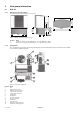
3.1.2 Components
The component image below shows diagrammatically how the heat pump looks inside. There may be differ-
ences between different versions.
Figure 2: Components in DHP-AX.
Position Name
1 Fan
2 Operating pressostat
3 High pressure pressostat
4 Low pressure pressostat
5 2-way expansion valve
6 Drying filter
7 Compressor
8 Air heat exchanger
9 Electrical cabinet
10 Condenser
11 Four way valve
12 Heating system supply line
13 Return line heating system
1
2
1167
661
405
495 76
325
243
1250
773
10
11
1
8
9
2
3
7
4
13
5
12
6