
Specifications


50 – Service VMBMH302
Problem – Alarm MS (motor protection)
Cause Troubleshooting Remedy
1. Phase drop or blown fuse. Check that all phases are present on the
terminal block for incoming supply. If
not, check the fuses in the cabinet.
Also check that all wiring is secure, if
screw terminals are used they must be
properly tightened, if phoenix flat spring
terminals are used, the cables must be
secure in the correct hole with load on
the cable.
If any of the phases are not present,
check backwards towards the building’s
main electrical cabinet. If there are no
phases there, contact the network supp-
lier.
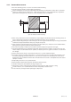
2. Defective soft-starter. Measurement check and establish that
when the I/O card gives a signal (there
must be voltage between A1 & A2 on the
soft-starter), the soft-starter releases all
three phases down to the compressor.
If the soft-starter does not release the
phases when it receives signals from the
I/O card, replace it.
3. Defective contactor. Measurement check and establish that
when the I/O card gives a signal (there
must be voltage between A1 & A2 on the
contact), the contact releases all three
phases down to the compressor.
If the contact does not release the pha-
ses when it receives signals from the I/O
card, replace it.
4. Defective or incorrectly set
motor protection.
Use a hook-on meter to establish when
the motor protection deploys, check
what the motor protection is set to.
Compare with the table.
If the motor protection is defective,
replace it.
If incorrectly set, adjust to the correct
value.
5. Cable break. Check the supply to the motor protec-
tion//soft-starter/compressor.
If a cable is damaged, replace it.
6. Defective compressor. Measurement check the voltage on the
three phases (each to zero) at the com-
pressor. Deviations from the average of
the three values should not be more than
12% on any of the phases. If measure-
ment checking the winding’s impedance
the same value must be on all three
windings.
If the compressor is defective, replace it.
Problem – Alarm sensor (all)
Cause Troubleshooting Remedy
Sensor fault alternatively cable
fault.
• When reading the resistance of the sen-
sors, the sensor leads must first be dis-
connected from the control equipment
or terminal block.
• First take a reading from the sensor
including cable and check against the
ohm table in section 15.3 Measurement
points.
• If the read off value does not cor-
respond with the table, only measure the
sensor and check the ohm table in sec-
tion 15.3 Measurement points.
If the sensor gives a correct value, the
cable is defective.
If the sensor does not give a correct
value, the sensor is defective.