
Specifications


16 – Installation VMBMH302
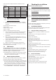
In the event of a surplus of heat the conditions are the
opposite:
ROOM
FACTOR
Increased
room tempe-
rature, °C
Actual room
temperature,
°C
Set point for
supply line,
°C
0 20 22 40
1 20 22 38
2 20 22 36
3 20 22 34
4 20 22 32
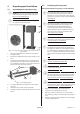
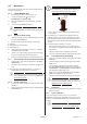
NOTE! The room temperature sensor is connect-
ed to a safety extra-low voltage.
1. Install the room temperature sensor in a location in
the house where the room temperature is relatively
constant:
Centrally located in the house
At eye level
Not in direct sunlight
Not in a draft
Not in a room with alternative heating
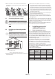
2. Hang a thermometer next to the room temperature
sensor in order to calibrate it after connecting it.
3. Connect the room sensor according to the electrical
instructions.
4. After connecting the room temperature sensor, it is
calibrated by holding in both buttons for 15 seconds
until the display starts to flash.
5. Set the actual room temperature that the
thermometer shows.
6. Wait 10 seconds until the display stops flashing.
If the display shows “--” for outdoor temperature no out-
door temperature has been read.
7.2 EVU function
The EVU function prevents the operation of HEAT PUMP
and AUX. HEATER as long as the contact is closed. The text
EVU STOP is shown in the display when this function is
active. The integral is calculated as normal.
The EVU function is activated by connecting according
to the electrical instructions as well as by connecting
an external 1-pin timer for example.
7.3 Room setpoint reduction
The room setpoint reduction function provides a regular,
temporary reduction of the indoor temperature.
The room setpoint reduction function is activated using
the same connection as for the EVU function according
to the electrical instructions, and with the aid of a 10
kohm resistor and an external 1-pin timer for example.
The extent of the room setpoint reduction is set in the
menu INFORMATION -> HEAT CURVE -> REDUCTION.
8 Checking the installation
NOTE! Read the safety instructions!
The installation may only be commissioned if
the heating system and water heater have been
filled and bled. Otherwise the circulation pumps
can be damaged.
Any alarms that may occur in connection with
the installation can be fault-traced in the 15
Troubleshooting section in the service instructions.
8.1 Starting before the installation is
complete
For further information about the heat pump’s control sys-
tem, see section 12 Control panel.
8.2 Installation checklist
Before manual test operation, the following points must
be checked so that they are carried out:
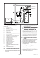
8.2.1 Piping installation, heating system
Pipe connections in accordance with the connection
diagram
Flexible hoses on the supply and return lines
Pipe insulation
Strainer on return line
Bleeding the heating system
All radiator valves fully open
Expansion tank heating system (not included in the
delivery)
Safety valve for expansion tank
Filler cock, heating system (not included in the delivery)
Leakage inspection
Safety valve for cold water (9 bar) (not included in the
delivery)
If an external water heater is installed, also check:
Exchange valve (not included in the delivery)
Bleed valve (not included in the delivery)
8.2.2 Electrical Installation
Circuit-breaker (not included in the delivery)
Fuse protection
Direction of rotation of the compressor
Positioning of the outdoor sensor
Control computer settings
If an external water heater is installed, also check:
Exchange valve (not included in the delivery)