Danfoss DHP-AX Installation and Service instructions VMBMH302
These instructions are valid for the following model of Danfoss heat pump: DHP-AX If these instructions are not followed during installation and service, Danfoss AS’s liability according to the applicable warranty is not binding. Danfoss AS retains the right to make changes to components and specifications without prior notice. © 2009 Copyright Danfoss AS.
1 2 3 4 5 6 7 8 9 About the instructions . . . . . . . . . . . . . . . . . . . . . . . . . . . . . . . . . . . . . . 4 11 The heat pump . . . . . . . . . . . . . . . . . . . . . . . . . . . . . . . . . . . . . . . . . . . . 21 1.1 Introduction . . . . . . . . . . . . . . . . . . . . . . . . . . . . . . . . . . . . . . . . . . . . . . . . 4 11.1 Function description . . . . . . . . . . . . . . . . . . . . . . . . . . . . . . . . . . . . . . . 21 1.2 Symbols . . . . . . . . . . . . . . .
1 About the instructions 1.3 1.1 Introduction The instructions contain terms throughout that designate components and functions. The table lists the most common terms that are used in the instructions. These instructions are split into two parts: installation instructions and service instructions. The installation instructions start by describing DHP-AX data.
DD Bleed valves must be installed where necessary. DD Radiator systems with closed expansion tanks must also be supplied with approved pressure gauges and safety valves. DD Cold and hot water pipes and overflow pipes from safety valves must be made of heat resistant and corrosion-resistant material, e.g. copper. The safety valve overflow pipes must have an open connection to the drain and visibly flow into this in a frost-free environment. DD 2.
BB EE Hazardous electrical voltage! The terminal blocks are live and can be highly dangerous due to the risk of electric shock. All power supplies must be isolated before electrical installation is started. The heat pump is connected internally from the factory, for this reason electrical installation consists mainly of the connection of the power supply. The room temperature sensor is connected to a safety extra-low voltage.
Installation instructions VMBMH302 Service – 7
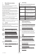
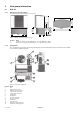
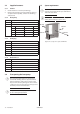
3.1 DHP-AX 3.1.1 Dimensions and connections The stand shown in the image is an accessory. 661 Heat pump information 76 1250 3 495 405 773 1 243 1167 2 325 Figure 1: DHP-AX, dimensions and connections. Position 1 2 3.1.2 Name Supply line heating system, DHP-AX 6, 8, 10: 22 Cu, DHP-AX 12: 28 Cu Return line heating system, DHP-AX 6, 8, 10: 22 Cu, DHP-AX 12: 28 Cu Components The component image below shows diagrammatically how the heat pump looks inside.
3.
3.3 Supplied contents 3.5 3.3.1 Control 1. Check that there is no transport damage. 2. Remove the packaging and check that the delivery, except for the heat pump, contains the following components. 3.3.2 Heat pump DD To ensure the function of the heat pump, there must be at least 300 mm of space behind and 1500 mm at the front. EE For maintenance work there must be approximately 300 mm of space at the sides.
4 Unpacking and installation 4.2 4.1 Assembling the stand (accessory) When positioning the heat pump, note the following: DD DD NOTE! Only place the heat pump on its short side as shown in the figure below, otherwise there is a risk of damaging it. NOTE! All panels (except the front cover) must be installed on the heat pump. Positioning the heat pump DD The heat pump must be positioned some distance away from the ground as the defrost function can cause ice build-up.
5 Piping installation DD NOTE! To prevent leaks, ensure that there are no stresses in the connecting pipes! DD NOTE! It is important that the heating system is bled after installation. Bleed valves must be installed where necessary. DD Piping installation must be carried out in accordance with applicable local rules and regulations. The hot water tank must be equipped with an approved safety valve (supplied). EE The pipes between the heat pump various units should be isolated.
33 72 21 Heating circuit 2 56 80 Heating circuit 1 80 112 87 82 85 77 80 Cold water Hot water 50 36 40 55 51 18 99 114 53 96 5 102 52 54 91 84 96 5.1.1 5.3 DHP-AX, VL system Connecting the heating system supply and return lines Figure 7: General connection diagram.
6 Electrical Installation BB AA DD Electrical components in 230V 1N control centre Electrical current! The terminal blocks are live and can be highly dangerous due to the risk of electric shock. All power supplies must be isolated before electrical installation is started. The heat pump is connected internally at the factory, for this reason electrical installation consists mainly of the connection of the power supply.
zzWhen the cable is connected to the terminal block a screwdriver is used to open the terminal block, see figure below. 2 1 3 5 OK! 4 Figure 10: Connecting cable to terminal block. 6.3 BB 6.4 Electrical current! The power cable may only be connected to the terminal block intended for this purpose. No other terminal blocks may be used! Positioning and connecting outdoor sensors NOTE! The outdoor sensor is connected with extra low protection voltage.
8 In the event of a surplus of heat the conditions are the opposite: ROOM FACTOR 20 22 40 1 20 22 38 2 20 22 36 3 20 22 34 4 20 22 32 DD NOTE! Read the safety instructions! Increased Actual room Set point for room tempe- temperature, supply line, rature, °C °C °C 0 NOTE! The room temperature sensor is connected to a safety extra-low voltage.
8.3 Manual test Test operate and at the same time check the function of the tested components. AA 8.3.1 Activate MANUAL TEST 1. Ensure that the main circuit breaker is on. 2. Select operating mode , in the menu INFORMATION -> OPERAT.-> 3. Open the SERVICE menu by holding in for five seconds. 4. Set the value for MANUAL TEST to 2. EE Select position 2 to navigate away from the MANUAL TEST menu during ongoing test operation.
9.2.1 Follow the instructions below to perform a calibration. 1. Detach and remove any insulation by the sensor to be calibrated. 2. Connect a thermometer by the sensor. 3. Note the actual temperature. 4. Open the INFORMATION menu by pressing the left or right button once. 5. Open the TEMPERATURE menu. 6. Note the sensor’s measured temperature. 7. Compare the actual and measured temperatures. If there is a difference, the sensor requires calibrating as follows. 8.
10 Customer information After installation and test operation, the customer must be informed about their new heat pump installation.
Service instructions 20 – Service VMBMH302
11 The heat pump 11.1 Function description A heat pump utilises the free energy from the sun and that is found in a natural heat source, such as rock, ground, ground water or air. The heat pump can be compared to a reversed refrigerator; in a refrigerator heat is transferred from the inside of the refrigerator to the outside, whereas in a heat pump, the stored solar energy that is stored in a heat source is transferred to the inside of the house.
11.2 Heating and defrost functions 11.2.1 Heating DHP-AX is a heat pump that can produce heating for houses and water heaters. Hot water production is active all year round but during the summer heat production to the house is stopped when the outdoor temperature reaches the value for HEAT STOP. Pressostat Low pressure Service output Pressure pipe sensor Pressostat High pressure Hot Bulb Cold Compr.
11.2.2 Defrost function During operation the air heat exchanger is cooled by the energy exchange at the same time as the humidity causes it to become covered in frost. DHP-AX has an automatic function to defrost the air heat exchanger using the produced heat energy.
The heat pump unit consists of the following basic units: 1 Heat pump unit zzCompressor zz2-way expansion valve zzCondenser, stainless steel heat exchanger zz4-way valve 2 Fan zzOne speed 3 Air heat exchanger Exchanger with copper pipes and hydrophilic aluminium fins.
At outdoor temperatures colder than 0°C, supply water hotter than 40°C is sent out to the heating system and at outdoor temperatures greater than 0°C, supply water cooler than 40°C is sent out. Supply temperature Maximum supply temperature Outdoor temperature Figure 20: Increasing or reducing the CURVE changes the slope of the curve If you increase the CURVE value, the heat curve will become steeper and when you reduce it, it will become flatter.
Supply temperature Local higher supply temperature at -5° Outdoor temperature Figure 22: The adjusted curve at -5°C Sometimes, at outdoor temperatures between -5°C and +5°C, part of the heat curve may need adjusting if the indoor temperature is not constant. For this reason, the control system includes a function adjusting the curve at three outdoor temperatures: -5°C, 0°C, +5°C.
The integral value is a measurement of the surface under the time axle and is expressed in degree minutes. The figure below shows the factory settings for the integral values that the heat pump has. When the integral value has reached the set value for INTEGRAL A1, the compressor starts and if the integral value does not drop but continues to rise, the auxiliary heater starts when the integral value has reached the set value for INTEGRAL A1+A2.
11.5.9 DEFR CURVE To start defrosting the outdoor unit, the control system makes a calculation using the temperature of the incoming refrigerant and the outdoor temperature. What guides the calculation is a linear defrosting curve that can be set so that the heat pump and outdoor unit work optimally. The setting of three different values can be changed: DEFR CURVE 0 , DEFR CURVE –20 and OUTDOOR STOP.
12 Control panel 12.1 Function description The heat pump has an integrated control system that is used to automatically calculate the heat demand in the house where the heat pump is installed and to ensure that the correct amount of heat is produced and emitted where necessary. There are many different values (parameters) that must be referred to during the calculation of the heat demand.
The indicator at the bottom of the control panel has two modes: zzLit continuously, the heat pump has power and is ready to produce heat or hot water zzFlashing, means an active alarm DD 12.2 NOTE! During a service that consists of replacing the display card, all heat pump settings are lost. If possible, note all specific settings for the customer’s heat pump before replacement. Display The display shows information about the heat pump’s operation, status and any alarms, in text form.
Symbol 12.2.4 Meaning DEFROST Displayed when defrosting is active. FAN Displayed when the fan is active. Operational information Shows text information about the heat pump. Message Meaning ROOM Shows the set ROOM value. Standard value: 20°C. If the accessory room sensor is installed it shows the actual temperature and the indoor temperature within brackets. START Indicates that there is a need for heat production and that the heat pump will start.
13 Menu information 13.1 INFORMATION menu This menu is used to change the heat pump’s operating modes and adjust the heat curve. History and operating times can also be viewed here. Open the menu by pressing the left or right button. The sub menus always available in the INFORMATION menu are shown in the following table in bold: Menus in italics are only visible if the expansion card and certain sensors are installed. Menu Sub menu Selection/settings INFORMATION OPERAT. Ø AUTO HEAT PUMP AUX.
13.1.1 Sub menu INFORMATION -> OPERATION Used to select operating mode. Menu selection (OFF) Meaning Factory setting The installation is off. This mode is also used to acknowledge certain alarms. - CANCEL = starting point, no changes made. To select OFF as operating mode, press the minus sign once to scroll down one step and press the right arrow once. AUTO Automatic operation with both heat pump and auxiliary heater permitted.
13.1.3 13.1.4 Menu selection Meaning Factory setting POOL (Expansion card) Only appears if POOL is selected. The temperature in the pool is controlled by a separate sensor regardless of the heating and hot water system. 20°C (interval: POOL HYSTERESIS (Expansion card) Only appears if POOL is selected. In simple terms, the POOL HYSTERESIS is the temperature interval between start and stop for pool heating.
13.1.5 Sub menu INFORMATION -> OPERAT. TIME Used to show the operating time for each component. Time given in hours. Menu selection Meaning Factory setting HEAT PUMP Compressor operating time for both heating and hot water production. Operating time auxiliary heat step 1. Operating time hot water with compressor. - AUX. HEAT 1 HOT WATER 13.1.6 - Sub menu INFORMATION -> DEFROST This menu is used to obtain information about outdoor unit defrosting and to make certain settings.
13.2 SERVICE menu This menu is for use during installation and service to optimise and adjust the operation of the heat pump. Open the menu by holding the left button in for five seconds. The sub menus always available in the SERVICE menu are shown in the following table in bold: Menus in italics are only visible if the expansion card is installed. Menu Sub menu Selection/settings SERVICE HOT WATER HEAT PUMP AUX. HEATER MANUAL TEST INSTALLATION START HOT WATER TIME HEATING TIME TOPH. INTERVAL TOPH.
13.2.1 13.2.2 13.2.3 Sub menu SERVICE -> HOT WATER Used to change the settings for hot water production. Menu selection Meaning Factory setting START Start temperature for hot water production. Shows the actual weighted hot water temperature and the value within brackets indicates the start temperature. ( = no sensor alarm) (interval: , 30°C / 55°C) HOT WATER TIME Time for hot water production during combined hot water and heating demand, in minutes.
13.2.4 Menu selection Meaning Factory setting HYSTERESIS If the difference between the actual supply temperature and the calculated supply temperature is too great (see section 11.5 Important parameters), either the integral value is set to start value A1 + A2 (starts the auxiliary heater) or the value is set to 0 (stops the auxiliary heater ). 20°C (interval: 5°C / 30°C) MAX CURRENT (Expansion card) Refers to main fuse in the unit, in amperes.
13.2.5 Sub menu SERVICE -> INSTALLATION Used for settings that are set during installation. Menu selection Meaning Factory setting ENGLISH Language setting for the control system. ENGLISH The button sequence that is to be pressed to access this menu to (ÈEŠTINA, change language is shown here: POLSKI, (5 seconds), , , , , , . You are now in the language menu, select language using or SYSTEM Note! The menu selection in the SYSTEM menu varies depending on the selected values.
Menu selection Meaning Factory setting VERSION Shows the software version which is stored on the display card respectively the I/O-card. - DISPLAY: V n.n I/O-CARD: V n.n LOG TIME Time interval between collection points of temperature history in minutes. The history graphs always show the 60 last collection points, which means that the graphs can display history from 1 hour up to 60 hours ago. 1M (interval: 1M / 60M) (The function is not active if there is an active alarm). TOPH. TIME 13.2.
VMBMH302 Service – 41
14 Noise information 14.1 Flexible hoses All pipes should be routed in such a way that vibrations cannot be transmitted from the heat pump through the piping and out into the building. This also applies to the expansion pipe. To avoid the transmission of vibrations, we recommend that flexible hoses are used for the supply line and return line on both the heating system and brine system sides. Flexible hoses are available to purchase as accessories.
Preventative measures ØD Some of the following points can also be used when troubleshooting. zzDo not install heat pumps on walls adjoining bedrooms. zzEnsure that all pipes are elastically suspended, with mountings as illustrated or similar. This is so that the rubber (or similar material) compresses 1–2 mm under vibration. It is not recommended to suspend the pipes from too many points, as the force at each mounting is then not sufficient. G 14.2 h1 H h2 Figure 33: Example of rubber mounting.
15 Troubleshooting 15.1 Alarm Shown in display in the event of an alarm. To reset alarms 1-5, set the operating mode to OFF or cut the power supply. Message Meaning HIGH PRESSURE ERROR Tripped high pressure switch. Compressor stopped. No hot water production. LOW PRESSURE ERROR Tripped low pressure switch. Compressor stopped. No hot water production. MOTOR P ERROR Deployed motor protection (Over current relay compressor), or deployed motor protection for outdoor unit fan. Compressor stopped.
15.2 Measurement points Conversion table for sensors DD When reading the resistance of the sensors, the sensor leads must first be disconnected from the control equipment. Outdoor sensor 15.
Break pressure pressure switches 15.4 EE Refrigerant Pressostat Break pressure R407C Low pressure pressostat 0.08 MPa Operating pressure switch A 2.65 MPa Operating pressure switch B 2.85 MPa High pressure pressostat 3.10 MPa Operational problems The tables in the following section apply to all types of heat pump and collector solutions. This means that certain information does not apply to DHP-AX. The tables have the most probable and most common causes of the problem listed first.
Cause Troubleshooting Remedy 8. Incorrect mix of anti-freeze, the concentration must be in accordance with instructions. Check the freezing point of the mix using a refractometer. If the mixture is not in accordance with the instructions, it must be remixed in an external container. This is because the fluids do not mix with each other well if one is filled directly into the system. 9. Short active collector, e.g. short or dry bore hole, short surface soil collector.
Cause Troubleshooting Remedy 15. Blocked evaporator on the refrigerant side. Using manometer apparatus and thermometer, check that the unit’s overheating is correct for the specific refrigerant. If the evaporator is thought to be blocked by oil for example, try blowing nitrogen through it to release the oil. If this does not work, it must be replaced Problem – Alarm HP (high pressure pressure switch) Cause Troubleshooting Remedy 1. Blocked strainer in the heating system.
Cause Troubleshooting Remedy 9. External system shunt that clo- Check for shunts or valves in the system, ses on time setting. which are timer-controlled, that close down the entire or too large a part of the heating system. Always ensure that there is a sufficiently large water volume for the heat pump to work against, i.e. for the heat to give off its heat to. 10. Incorrectly facing non-return valve with too high opening pressure.
Problem – Alarm MS (motor protection) Cause Troubleshooting Remedy 1. Phase drop or blown fuse. Check that all phases are present on the terminal block for incoming supply. If not, check the fuses in the cabinet. If any of the phases are not present, check backwards towards the building’s main electrical cabinet. If there are no phases there, contact the network supplier.
Problem – Incorrect phase sequence Cause Troubleshooting Remedy The incoming phases have the incorrect sequence (only applies to 3-phase heat pumps). • If the text ERR PHASE SEQ. appears in the display when the heat pump is powered, (only appears in the first 10 minutes) this means that the phases have the incorrect sequence. If the phases are in the incorrect order, switch two incoming phases at the main terminal block and recheck according to the troubleshooting window.
Cause Troubleshooting Remedy 2. Brine temperature too low. Check the set value on ALARM BRINE in the heat pump’s control computer. The alarm is triggered when the temperature on BRINE OUT is as low or lower than the set value on ALARM BRINE. In the factory setting this function is inactive. Problem – Alarm Brine flow low Cause Troubleshooting Remedy 1. Incorrect system selected in the control system. In the menu SYSTEM, check which is selected. If the incorrect system is selected, change it.
Cause Troubleshooting Remedy 4. Overheating too high. Using manometer apparatus and thermometer check what the overheating reading of the unit is. If the overheating reading does not correspond with the instructions for the specific refrigerant, adjust the expansion valve until the correct value is obtained. See separate instructions for cooling techniques. Also check that bulb and capillary tube are undamaged and that the bulb is correctly installed.
Cause Troubleshooting Remedy 11. Leak at soldered joint on water heater. Locate the leak. If there is a leak at the soldered joint, replace the water heater. 12. Associated leak on the water heater. • Establish whether water continuously leaks from the safety valve on the expansion vessel on the hot side. If the water heater has a leak, replace it. • Establish whether water continuously leaks from the safety valve on the cold side. 13. Associated leakage in the condenser.
Problem – Loud compressor noise Cause Troubleshooting Remedy 1. Phase drop. 1. Check that there is 400 V between incoming phases on the heat pump. Check where the phase drop is and rectify. 2. Touching pipes – vibrations. Establish which pipe(s) is/are causing the problem. Try to release any tensions that cause the vibrations. 3. Compressor fault. Determine whether the compressor is unusually loud. If the compressor is defective, replace it.
15.4.4 Hot water Problem – Temperature and/or quantity Cause Troubleshooting Remedy 1. Defective 3-way valve motor. Check the function of the 3-way valve, that it runs between the end positions by running a manual test. If the motor is defective, replace it. 2. Jammed 3-way valve insert. Detach the motor and test closing and opening of the valve by pressing the The valve is not secure and relea- control arm ses hot water to the radiators during hot water production.
Cause Troubleshooting Remedy 10. Heat loss in the hot water pipe. Open the hot water tap, read off the temperature on the outgoing hot water pipe from the heat pump and the temperature of the hot water. The temperature difference measured between the heat pump and hot water indicates the temperature loss. If any problems occur during troubleshooting as per the points, carry out corrective actions. Examples of temperature loss causes: • Long water pipes. • Uninsulated hot water pipes.
Cause Troubleshooting Remedy 6. The heat pump has stopped on HIGH RETURN. • Check what the MAX RETURN value is set at in the heat pump’s control computer. It must be adjusted to the unit’s maximum supply temperature and the system’s delta temperature so that it does not cut at too high a return temperature when the highest supply temperature is transmitted. If the MAX RETURN value is not adjusted for the system according to the troubleshooting window, adjust it. If the sensor is defective, replace it.
Cause Troubleshooting Remedy 12. Changed conditions • If the heat pump has been dimensioned for a certain demand and this demand is increased, the heat pump might not be able to maintain the desired room temperature. If the heat pump cannot cope with the demand, replace it with one with a higher output or supplement it with a higher output auxiliary heater.
Problem – irregular indoor temperature Cause Troubleshooting Remedy 1. The heat pump’s control computer is not set/adjusted to the customer’s requirements/wishes. Check the ROOM and CURVE, MIN, MAX CURVE5, CURVE0, CURVE‑5 and HEAT STOP settings. Adjust incorrect values in the heat pump’s control computer. ROOM = Desired indoor temperature CURVE = Should be set so that the desired indoor temperature (ROOM) is maintained regardless of the outdoor temperature.
Problem – Runs on electric heating element Cause Troubleshooting 1. Operating mode AUX. HEATER is selected. If this operating mode is selected, the aux- If AUX. HEATER mode is selected and you iliary heater is used for heating and hot no longer want it, change to AUTO, the water production, not the compressor. heat pump then controls both the compressor and auxiliary heater. Remedy 2. The compressor cannot run due Check the alarm that is indicated in the to an alarm. display.
Problem – The auxiliary heater is in operation but not the compressor Cause Troubleshooting Remedy 1. Operating mode AUX. HEATER is selected. If this operating mode is selected, the auxiliary heater is used for heating and hot water production, not the compressor. If AUX. HEATER mode is selected and you no longer want it, change to AUTO, the heat pump then controls both the compressor and auxiliary heater. 2. Peak heat operation (anti-legionella function) is running.
Cause Troubleshooting Remedy 7. The compressor runs backwards. The incoming phases have the incorrect sequence (only applies to 3-phase heat pumps). If the compressor runs backwards, it will not cope with compressing the refrigerant and therefore does not produce the correct power, which leads to the control system requesting auxiliary heating. • If the text ERR PHASE SEQ.
Cause Troubleshooting Remedy 7. The heat pump has stopped on HIGH RETURN. • Check what the MAX RETURN value is set at in the heat pump’s control computer. It must be adjusted to the unit’s maximum supply temperature and the system’s delta temperature so that it does not cut at too high a return temperature when the highest supply temperature is transmitted. If the MAX RETURN value is not adjusted for the system according to the troubleshooting window, adjust it. If the sensor is defective, replace it.
Cause Troubleshooting Remedy 12. Overfilled refrigerant circuit. Using manometer apparatus and thermometer, check that the unit’s overheating is correct for the specific refrigerant. Follow the correct procedure (depending on type of refrigerant) to add the correct amount of refrigerant. 13. Short active collector, e.g. short or dry bore hole, short surface soil collector. • Check the length of the collector that is being used and compare with the collector length in the dimensioning documentation.
Cause Troubleshooting Remedy 5. Changed conditions Have you increased your heating and/or hot water demand? • If the heat pump has been dimensioned for a certain demand and this demand is increased, the heat pump might not be able to maintain the desired room temperature. If the heat pump cannot cope with the demand, replace it with one with a higher output or supplement it with a higher output auxiliary heater.
15.4.7 Outdoor unit Problem – Noise/loud noise Cause Troubleshooting Remedy 1. Positioning the outdoor unit. Determine whether the outdoor unit can be moved to a more suitable location. When positioning the outdoor unit, its direction does not affect its performance. The outdoor unit does not need to be positioned as close to the heat pump as necessary, it can be positioned as far as 30 ”pipe metres” way. 2. Connection/wall lead-ins. Check that the unit is installed according to the instructions.
– Service VMBMH302
VMBMH302 Service – 69
VMBMH302