
Specifications


24
VMBMA502
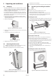
6 Piping installation
⚠
NOTE! To prevent leaks, ensure that there are no stresses in
the connecting pipes!
⚠
NOTE! It is important that the heating system is completely
bled after installation.
⚠
NOTE! The connection diagrams show general piping
arrangements. It is imperative that piping installation is
carried out in accordance with applicable local rules and
regulations. The hot water tank must be equipped with an
approved safety valve (supplied).
⚠
NOTE! Bleed valves must be installed where necessary.
• Ensurethatthepipinginstallationfollowsthedimensionand
connection diagrams in section “Heat pump information”.
• ForUKspecificadviceonpipingarrangementspleasereferto
the ‘UK-specific appendix to Installation and Service Instructions'.
An approved safety valve is factory fitted to all single phase heat
pumps incorporating stainless steel hot water tanks.
• Thepositionlistsshowthecomponentsandpartsincludedinthe
delivery in italics.
Selecting the heating system
The heat pump is set to VL system on delivery, that is with an inte-
grated electrical auxiliary heater and an exchange valve after the
auxiliary heater.
What determines which of the three systems VL, D or VLD should
be used is, among other things, how any auxiliary heater is used for
hot water production, and which model of heat pump is used.
6.1 VL system
In a VL system the heat pump can produce both heating and hot
water with the compressor and the integrated auxiliary heater.
Production of heating and hot water cannot occur at the same time
because the exchange valve for heating/hot water is positioned
after the auxiliary heater.
DHP-H, -C, -A, DHP-H Opti Pro, connection diagram VL
system
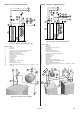
General connection diagram DHP-H, -C, -A, DHP-H Opti Pro.Figure 41:
Position Name
1 Supply line
2 Return line
3 Safety valve cold water (9 bar) (included in delivery)
4 Safety valve expansion heating system
5 Expansion heating system
6 Strainer (part of the delivery)
7 Flexible hoses (part of the delivery)
8 Vacuum valve
9 Non-return valve
10 Shut-off valve
11 Non-return valve
12 Shut-off valve
13 Hot water
14 Cold water
15 Heat pump (part of the delivery)
16 Pressure gauge
17 Expansion outlet Brine DHP-A
18 Safety valve for temperature and pressure (only applies to certain
markets)
19 Safety valve for temperature and pressure (only applies to certain
markets)
Principal pipe connection DHP-H, -C, -A, DHP-H Opti Pro..Figure 42:
5
7
6
1
2
12
17
3
19
13 14
4
16
18
1
2
3
4
5
8
9
10
14
18
11
12
13
15
7
6