
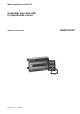
Installation guide

4 Menu operation RC.1N.H1.02 © Danfoss 06/96 AKC 24A Version 1.0x
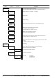
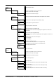
Level 1 Level 2 Level 3 Description
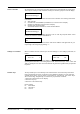
DANFOSS AKC 24 A Shows controller type, weekday and time
An E on the display means an error has been recorded.(See page 8)
1
Clock: Day Setting of week day (1 = Monday, 7 = Sunday)
(Mon)1 (Sun)7
1:01
|
Clock: Hour Setting of hours
0 23
1:02
|
Clock: Min. Setting of minutes
0 59
1:03
|
Code No. Reading of the actual controller code no. and programme version
Prog.Ver.
1:04
|
System address Reading of the actual controller system address
Addr. yyy xxx yyy=network no. and xxx=address.
1:05 The system address can only be set via PC
|
Address Reading of the actual controller’s address
xxx (Setting on the controller’s DIP-switch)
1:06
|
Alarm report to Reading of the system address (receiver) the alarms are to be sent to.
Addr. yyy xxx The system address can only be set via PC
1:07
|
Gateway Address Reading of the address on the nearest gateway which has to effect alarms
xxx (see 1:07).
1:08 The address can only be set via PC
|
Main Function Main function
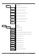
2
Alarm message Error log. The menu is only visible in case of an active error
(At alarm, an E is shown on the display)
2:01
See page 8 for list of alarm messages
2:01:01
|
Main Switch Access to the main switch.
Ctrl(1)/Serv(-1)
2:02
Main Switch Main switch: 1: Regulation
-1 / 0 / 1 0: Controller stop
2:02:01 -1: Service mode