Menu operation via AKA 21 Controller type AKC 24A for liquid level control Software version 1.0x RC.1N.H1.
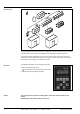
System survey A refrigerating plant fitted with ADAP-KOOL® refrigeration controls will mostly consist of several controllers where each controller will regulate its own refrigeration appliance/cold room. The system has been designed in such a way that contact can be made to each and every controller via a data communication system. One specific controller is selected, and it will now be possible to make settings and readouts for this unit.
Select a controller All controllers that are connected to the same network can be operated with the control panel. There may be as many as 125 controllers, and they are shown in groups of 16 on the display. 1 < 1 > 16 AEAAAAAAAAEEgg A A system is shown here which consists of more than 16 controllers.
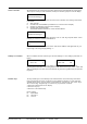
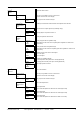
Level 1 Level 2 Level 3 DANFOSS AKC 24 A Description Shows controller type, weekday and time An E on the display means an error has been recorded.(See page 8) 1 Clock: Day (Mon)1 (Sun)7 1:01 | Clock: Hour 0 23 1:02 | Clock: Min. 0 59 1:03 | Code No. Prog.Ver. 1:04 | System address Addr. yyy xxx 1:05 | Address xxx 1:06 | Alarm report to Addr. yyy xxx Setting of week day (1 = Monday, 7 = Sunday) Setting of hours Setting of minutes Reading of the actual controller code no.
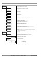
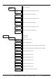
| Injection Control 3 Expansion valve function Alarm message Error log is only visible in case of an active error. At alarm an E is shown on the display. 3:01 See page 8 for list of alarm messages 3:01:01 | Injection Ctrl. Measurements 3:02 Reading of measurement values related to the expansion valve function Level % 3:02:01 Actual level in % of input signal size (measuring range) | AKV OD % 3:02:02 | Injection Ctrl.
| Digital Output Settings 4:03 DO1 - DO3 settings DO1 High % 0 100 4:03:01 | DO1 Del. s 0 300 4:03:02 | DO2 High % 0 100 4:03:03 | DO2 Del. s 0 300 4:03:04 | DO3 Low % 0 100 4:03:05 | DO3 Del.
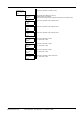
| Manual Control >> 5:02 Forced servo operation of outlets (service) Man. Ctrl. OFF ON 5:02:01 | AKV 1 % 0 100 5:02:02 | AKV 2 % 0 100 5:02:03 | AKV 3 % 0 100 5:02:04 | DO1 OFF ON 5:02:05 | DO2 OFF ON 5:02:06 | DO3 OFF ON 5:02:07 | Alarm Relay OFF ON 5:02:08 AKC 24A Version 1.
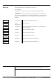
Error Log The following readouts are only visible if there is an active error AKA 21 operation: When the error is corrected, the error message can be removed by pressing ENTER. AKM operation: A sensor fault will activate the alarm output and a message will be sent out via DANBUSS®. The PC user of the AKM programm can set whether the other alarms are "to activate the alarm output and send via DANBUSS®", only "send via DANBUSS®" or "whether they are not to be displayed".