
User Manual


Installation Guide CCR3 Controller
55
Heating Solutions VI.D3.A2.02 DEN-SMT/SI
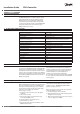
5. Control start menu
Start process
After switching the controller detected SD card on
and veried card memory.
If the card is placed correctly, the controller will verify
the present les:
• access
• one set
• all set
If the above-mentioned le is detected, the controller
will ask whether it should be used or aborted.
If no les (new card, used for the rst time) there will
be no request.
The next controller will automatically generate a folder
with les:
• folder ACCESS:
allow change of access code to menu (details on
request or www.danfoss.com side)
•
folder DATA: le with record date folder SETTINGS
with les
-
all set: le with settings. Each time the of control
is switched on, setting parameters are archived.
This function provides verication history of all
settings
- arch.set: le with archive of all settings.
Switching the controller on for the 2
nd
time with the
above-mentioned record le the request procedure
for setting change or abortion will start.
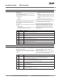
Display information during the start process
After switching the CCR3 Controller on, the LCD
display automatically presents the start menu.
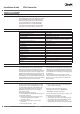
The table below shows the various information
and change possibilities during the operation of
CCR3 Controller.
No. LCD Display Description
1 Danfoss
OPCCR-3.12
Welcome Menu
Abbreviation: the type of the CCR3 Controller
2 SD Free
.....
Diagnosis: available SD card memory
3 SD Free
1996 MB
Available memory In MB
e.g.: 2 GB
4 NO
SD CARD!
No SD card in CCR3
Only when no card in CCR3
5 072254
123456
Series number of CCR3 and number of software.
Code used for services.
6 Thu On
12:59:32
Day of the week: Mon, Tue, Wed, Thu, Fri, Sat, Sun.
12:59:32 Real time: hour, minute, second
7 09-10-06
12:59:32
Real date
Real time: hour, minute, second
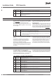
6. Control reading menu
When the setup is complete, the reading display will
be shown on the screen.
Pressing the “+” key turns the subsequent reading
display on. The “-” key turns the previous reading
display on.
No. LCD Display READING DESCRIPTION
8 Sensor0
…………
Current return temperature measure by sensors.
Information: S0 – supply temperature, S1-S16 – return temperature measure in risers.
When info display Sensor .... Open ( no sensor ), when : Sensor ..... Closed ( short cut ).
9 Valve1
…….
Status of control valves, display from V1-V16
Information:
0 % ON no control signal for actuators (valve fully open when NO is used) or 100 % OFF (valves is closed).
During the controlling intermediate status is displayed: e.g. 17 %
10 SetT R1
…….
Information about setting return temperature correspondent to current ow temperature, in C degree.
Display for R1-R16, e.g.: 45,0 °C
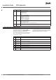
11 Time
………
Current date and time
e.g.: 10-04-27
17:45:10
12 Archiver
AC xx
Information about number of data storage in SD card(les)
e.g.: 38 storage le, InProces
xx = number of stored les; 1 le stored per day
Pressing an arrow “▲” result in exit from the reading
displays and enter to the ACCESS CODE menu,
described in chapter 7.
When exit from the menu the rst reading display
is shown. A list of readings and possible displayed
options are shown in the table below.